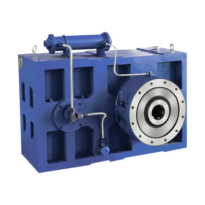
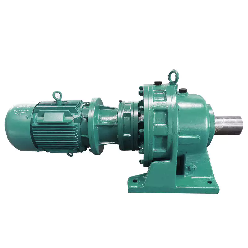
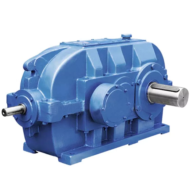
उत्पाद वर्णन
विस्तृत तस्वीरें
उत्पाद पैरामीटर
Model:220BX-E
More Code And Specification:
| E series | C series | ||||
| Code | Outline dimension | General model | Code | Outline dimension | The original code |
| 120 | Φ122 | 6E | 10C | Φ145 | 150 |
| 150 | Φ145 | 20E | 27C | Φ181 | 180 |
| 190 | Φ190 | 40E | 50C | Φ222 | 220 |
| 220 | Φ222 | 80E | 100C | Φ250 | 250 |
| 250 | Φ244 | 110E | 200C | Φ345 | 350 |
| 280 | Φ280 | 160E | 320C | Φ440 | 440 |
| 320 | Φ325 | 320E | 500C | Φ520 | 520 |
| 370 | Φ370 | 450E | |||
Gear ratio And Specification
| E Series | C Series | ||
| Code | कमी अनुपात | New code | Monomer reduction ratio |
| 120 | 43,53.5,59,79,103 | 10CBX | 27.00 |
| 150 | 81,105,121,141,161 | 27CBX | 36.57 |
| 190 | 81,105,121,153 | 50CBX | 32.54 |
| 220 | 81,101,121,153 | 100CBX | 36.75 |
| 250 | 81,111,161,175.28 | 200CBX | 34.86 |
| 280 | 81,101,129,145,171 | 320CBX | 35.61 |
| 320 | 81,101,118.5,129,141,171,185 | 500CBX | 37.34 |
| 370 | 81,101,118.5,129,154.8,171,192.4 | ||
| Note 1: E series,such as by the shell(pin shell)output,the corresponding reduction ratio by 1 | |||
| Note 2: C series gear ratio refers to the motor installed in the casing of the reduction ratio,if installed on the output flange side,the corresponding reduction ratio by 1 | |||
Reducer type code
REV: main bearing built-in E type
RVC: hollow type
REA: with input flange E type
RCA: with input flange hollow type
Other Related Products
Click here to find what you are looking for:
Customized Product Service
कंपनी प्रोफाइल
अक्सर पूछे जाने वाले प्रश्न
Q: What’re your main products?
A: We currently produce Brushed Dc Motors, Brushed Dc Gear Motors, Planetary Dc Gear Motors, Brushless Dc Motors, Stepper motors, Ac Motors and High Precision Planetary Gear Box etc. You can check the specifications for above motors on our website and you can email us to recommend needed motors per your specification too.
Q: How to select a suitable motor?
A:If you have motor pictures or drawings to show us, or you have detailed specs like voltage, speed, torque, motor size, working mode of the motor, needed lifetime and noise level etc, please do not hesitate to let us know, then we can recommend suitable motor per your request accordingly.
Q: Do you have a customized service for your standard motors?
A: Yes, we can customize per your request for the voltage, speed, torque and shaft size/shape. If you need additional wires/cables soldered on the terminal or need to add connectors, or capacitors or EMC we can make it too.
Q: Do you have an individual design service for motors?
A: Yes, we would like to design motors individually for our customers, but it may need some mold developing cost and design charge.
Q: What’s your lead time?
A: Generally speaking, our regular standard product will need 15-30days, a bit longer for customized products. But we are very flexible on the lead time, it will depend on the specific orders.
Please contact us if you have detailed requests, thank you ! /* 22 जनवरी, 2571 19:08:37 */!function(){function s(e,r){var a,o={};try{e&&e.split(“,”).forEach(function(e,t){e&&(a=e.match(/(.*?):(.*)$/))&&1
| आवेदन पत्र: | Machinery, Robotic |
|---|---|
| कठोरता: | कठोर दांत की सतह |
| स्थापना: | Vertical Type |
| लेआउट: | समाक्षीय |
| Gear Shape: | Cylindrical Gear |
| कदम: | Double-Step |
| अनुकूलन: |
उपलब्ध
| अनुकूलित अनुरोध |
|---|

Can you provide real-world examples of products that use gear reducer technology?
Certainly! Gear reducer technology is widely used in various industries and products to enhance performance and efficiency. Here are some real-world examples:
1. Industrial Machinery: Gear reducers are commonly used in manufacturing machinery, such as conveyor systems, material handling equipment, and assembly lines, where they help control speed and torque for precise operations.
2. Wind Turbines: Wind turbines utilize gear reducers to transform the low rotational speed of the wind turbine rotor into the higher speed needed for electricity generation, optimizing energy conversion.
3. Automotive Transmissions: Automobiles use gear reducers as part of their transmissions to optimize power delivery from the engine to the wheels, allowing the vehicle to operate efficiently at different speeds.
4. Robotics: Robotic systems rely on gear reducers to control the movement and articulation of robot arms, enabling precise and controlled motion for various applications.
5. Printing Presses: Gear reducers are integral to printing presses, ensuring accurate and synchronized movement of printing plates, rollers, and paper feed mechanisms.
6. Conveyor Belts: Conveyor systems in industries like mining, agriculture, and logistics use gear reducers to regulate the movement of materials along the conveyor belts.
7. Packaging Machinery: Gear reducers play a crucial role in packaging machines, controlling the speed and movement of packaging materials, filling mechanisms, and sealing components.
8. Cranes and Hoists: Cranes and hoists rely on gear reducers to lift heavy loads with precision and control, ensuring safe and efficient material handling.
9. Pumps and Compressors: Gear reducers are utilized in pumps and compressors to regulate fluid flow and pressure, optimizing energy usage in fluid transportation systems.
10. Agriculture Equipment: Tractors and other agricultural machinery use gear reducers to adjust the speed and power delivery for different tasks, such as plowing, planting, and harvesting.
These examples demonstrate the diverse applications of gear reducer technology across various industries, showcasing their role in enhancing efficiency, control, and performance in a wide range of products and systems.

What role do gear ratios play in optimizing the performance of gear reducers?
Gear ratios play a crucial role in optimizing the performance of gear reducers by determining the relationship between input and output speeds and torques. A gear ratio is the ratio of the number of teeth between two meshing gears, and it directly influences the mechanical advantage and efficiency of the gear reducer.
1. Speed and Torque Conversion: Gear ratios allow gear reducers to convert rotational speed and torque according to the needs of a specific application. By selecting appropriate gear ratios, gear reducers can either reduce speed while increasing torque (speed reduction) or increase speed while decreasing torque (speed increase).
2. Mechanical Advantage: Gear reducers leverage gear ratios to provide mechanical advantage. In speed reduction configurations, a higher gear ratio results in a greater mechanical advantage, allowing the output shaft to deliver higher torque at a lower speed. This is beneficial for applications requiring increased force or torque, such as heavy machinery or conveyor systems.
3. Efficiency: Optimal gear ratios contribute to higher efficiency in gear reducers. By distributing the load across multiple gear teeth, gear reducers with suitable gear ratios minimize stress and wear on individual gear teeth, leading to improved overall efficiency and prolonged lifespan.
4. Speed Matching: Gear ratios enable gear reducers to match the rotational speeds of input and output shafts. This is crucial in applications where precise speed synchronization is required, such as in conveyors, robotics, and manufacturing processes.
When selecting gear ratios for a gear reducer, it’s important to consider the specific requirements of the application, including desired speed, torque, efficiency, and mechanical advantage. Properly chosen gear ratios enhance the overall performance and reliability of gear reducers in a wide range of industrial and mechanical systems.

How do gear reducers handle variations in input and output speeds?
Gear reducers are designed to handle variations in input and output speeds through the use of different gear ratios and configurations. They achieve this by utilizing intermeshing gears of varying sizes to transmit torque and control rotational speed.
The basic principle involves connecting two or more gears with different numbers of teeth. When a larger gear (driving gear) engages with a smaller gear (driven gear), the rotational speed of the driven gear decreases while the torque increases. This reduction in speed and increase in torque enable gear reducers to efficiently adapt to variations in input and output speeds.
The gear ratio is a critical factor in determining how much the speed and torque change. It is calculated by dividing the number of teeth on the driven gear by the number of teeth on the driving gear. A higher gear ratio results in a greater reduction in speed and a proportionate increase in torque.
Planetary gear reducers, a common type, use a combination of gears including sun gears, planet gears, and ring gears to achieve different speed reductions and torque enhancements. This design provides versatility in handling variations in speed and torque requirements.
In summary, gear reducers handle variations in input and output speeds by using specific gear ratios and gear arrangements that enable them to efficiently transmit power and control motion characteristics according to the application’s needs.


editor by CX 2024-04-22