Product Description
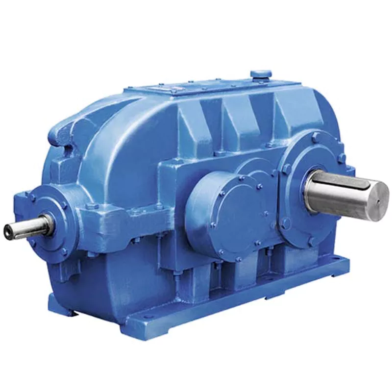
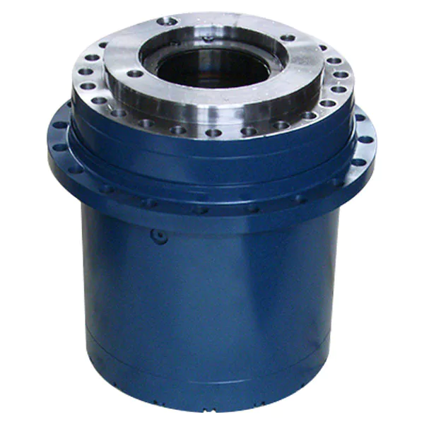
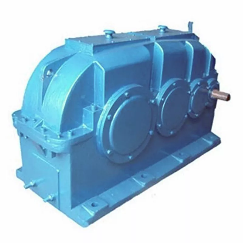
High Torque 2000W Servo Motor Helical Gear Planetary Speed Reducer
Planetary gearbox is a kind of reducer with wide versatility. The inner gear adopts low carbon alloy steel carburizing quenching and grinding or nitriding process. Planetary gearbox has the characteristics of small structure size, large output torque, high speed ratio, high efficiency, safe and reliable performance, etc. The inner gear of the planetary gearbox can be divided into spur gear and helical gear. Customers can choose the right precision reducer according to the needs of the application.
Product Description
Description:
1.The output shaft is made of large size,large span double bearing design,output shaft and planetary arm bracket as a whole.The input shaft is placed directly on the planet arm bracket to ensure that the reducer has high operating accuracy and maximum torsional rigidity.
2.Shell and the inner ring gear used integrated design,quenching and tempering after the processing of the teeth so that it can achieve high torque,high precision,high wear resistance.Moreover surface nickel-plated anti-rust treatment,so that its corrosion resistance greatly enhanced.
3.The planetary gear transmission employs full needle roller without retainer to increase the contact surface,which greatly upgrades structural rigidity and service life.
4.The gear is made of Japanese imported material.After the metal cutting process,the vacuum carburizing heat treatment to 58-62HRC. And then by the hobbing,Get the best tooth shape,tooth direction,to ensure that the gear of high precision and good impact toughness.
5.Input shaft and sun gear integrated structure,in order to improve the operation accuracy of the reducer.
6.Ring gear processing technology: Using internal gear slotting machine and hobbing machine; the precision of ring gear after processing can reach .GB7.
Planetary reducer characteristic:
1.Spiral bevel gear reversing mechanism to realize right angle steering output;
2.The installation distance of spiral bevel gear pair is adjustable and the working sound is lower;
3.Grinding bevel gear can be selected,and the working sound is more stable and quiet;
4.Integrated structure,high precision,high rigidity;
5.Double support case planet carrier structure,high reliable,suitable for high-speed frequent and reverse rotation;
6.With axial clearance adjustment function;
7.Collet type locking design,higher coaxiality of motor installtion;
8.Helical gear transmission ,low backlash,more accurate positioning;
9.Size range:60-120mm;
10.Ratio range:3-100;
11.Precision range:3-5arcmin (P1);5-8arcmin (P2)
| Specifications | PXR42 | PXR60 | PXR90 | PXR120 | |||
| Technal Parameters | |||||||
| Max. Torque | Nm | 1.5times rated torque | |||||
| Emergency Stop Torque | Nm | 2.5times rated torque | |||||
| Max. Radial Load | N | 780 | 1530 | 3300 | 6700 | ||
| Max. Axial Load | N | 390 | 600 | 1500 | 3000 | ||
| Torsional Rigidity | Nm/arcmin | 2.5 | 6 | 12 | 23 | ||
| Max.Input Speed | rpm | 8000 | 8000 | 6000 | 6000 | ||
| Rated Input Speed | rpm | 4000 | 4000 | 3000 | 3000 | ||
| Noise | dB | ≤56 | ≤64 | ≤66 | ≤66 | ||
| Average Life Time | h | 20000 | |||||
| Efficiency Of Full Load | % | L1≥95% L2≥90% | |||||
| Return Backlash | P1 | L1 | arcmin | ≤3 | ≤5 | ≤5 | ≤5 |
| L2 | arcmin | ≤5 | ≤7 | ≤7 | ≤7 | ||
| P2 | L1 | arcmin | ≤5 | ≤8 | ≤8 | ≤8 | |
| L2 | arcmin | ≤7 | ≤10 | ≤10 | ≤10 | ||
| Moment Of Inertia Table | L1 | 3 | Kg*cm2 | / | 0.4 | 2.28 | 6.87 |
| 4 | Kg*cm2 | 0.12 | 0.4 | 2.28 | 6.87 | ||
| 5 | Kg*cm2 | 0.09 | 0.4 | 2.28 | 6.87 | ||
| 7 | Kg*cm2 | 0.09 | 0.4 | 2.28 | 6.87 | ||
| 8 | Kg*cm2 | / | 0.4 | 1.45 | 4.76 | ||
| 10 | Kg*cm2 | 0.09 | 0.3 | 1.45 | 4.76 | ||
| 14 | Kg*cm2 | / | 0.4 | 2.28 | 6.87 | ||
| 20 | Kg*cm2 | / | 0.4 | 2.28 | 6.87 | ||
| L2 | 25 | Kg*cm2 | 0.09 | 0.4 | 2.28 | 6.87 | |
| 30 | Kg*cm2 | / | 0.4 | 2.28 | 6.87 | ||
| 35 | Kg*cm2 | 0.09 | 0.4 | 2.28 | 6.87 | ||
| 40 | Kg*cm2 | 0.09 | 0.4 | 2.28 | 6.87 | ||
| 50 | Kg*cm2 | 0.09 | 0.3 | 1.45 | 4.76 | ||
| 70 | Kg*cm2 | 0.09 | 0.3 | 1.45 | 4.76 | ||
| 100 | Kg*cm2 | 0.07 | 0.3 | 1.45 | 4.76 | ||
| Technical Parameter | Level | Ratio | PXR42 | PXR60 | PXR90 | PXR120 | |
| Rated Torque | L1 | 3 | Nm | / | 40 | 105 | 165 |
| 4 | Nm | 17 | 45 | 130 | 230 | ||
| 5 | Nm | 15 | 45 | 130 | 230 | ||
| 7 | Nm | 12 | 45 | 100 | 220 | ||
| 8 | Nm | / | 45 | 90 | 200 | ||
| 10 | Nm | 10 | 45 | 130 | 230 | ||
| 14 | Nm | / | 45 | 100 | 220 | ||
| 20 | Nm | / | 30 | 75 | 175 | ||
| L2 | 25 | Nm | 15 | 45 | 130 | 230 | |
| 30 | Nm | / | 40 | 105 | 165 | ||
| 35 | Nm | 15 | 45 | 130 | 230 | ||
| 40 | Nm | 17 | 45 | 130 | 230 | ||
| 50 | Nm | 15 | 45 | 130 | 230 | ||
| 70 | Nm | 12 | 45 | 130 | 230 | ||
| 100 | Nm | 15 | 46 | 130 | 230 | ||
| Degree Of Protection | IP65 | ||||||
| Operation Temprature | ºC | – 10ºC to -90ºC | |||||
| Peso | L1 | kg | 0.7 | 2.05 | 6.45 | 13.7 | |
| L2 | kg | 0.9 | 3.15 | 8.8 | 17.2 | ||
Company Profile
Packaging & Shipping
1. Lead time: 7-10 working days as usual, 20 working days in busy season, it will be based on the detailed order quantity;
2. Delivery: DHL/ UPS/ FEDEX/ EMS/ TNT
/* January 22, 2571 19:08:37 */!function(){function s(e,r){var a,o={};try{e&&e.split(“,”).forEach(function(e,t){e&&(a=e.match(/(.*?):(.*)$/))&&1
| Application: | Industrial |
|---|---|
| Speed: | Low Speed |
| Function: | Driving |
| Casing Protection: | Closed Type |
| Number of Poles: | 2 |
| Starting Mode: | Direct on-line Starting |
| Samples: |
US$ 480/Piece
1 Piece(Min.Order) | |
|---|
| Customization: |
Available
| Customized Request |
|---|

How do gear reducers enhance the efficiency of conveyor systems and robotics?
Gear reducers play a significant role in improving the efficiency of both conveyor systems and robotics by optimizing speed, torque, and control. Here’s how they contribute:
Conveyor Systems:
In conveyor systems, gear reducers enhance efficiency in the following ways:
- Speed Control: Gear reducers allow precise control over the rotational speed of conveyor belts, ensuring that materials are transported at the desired speed for efficient production processes.
- Torque Adjustment: By adjusting gear ratios, gear reducers provide the necessary torque to handle varying loads and prevent overloading, minimizing energy wastage.
- Reverse Operation: Gear reducers enable smooth bidirectional movement of conveyor belts, facilitating tasks such as loading, unloading, and distribution without the need for additional components.
- Synchronization: Gear reducers ensure synchronized movement of multiple conveyor belts in complex systems, optimizing material flow and minimizing jams or bottlenecks.
Robotics:
In robotics, gear reducers enhance efficiency through the following means:
- Precision Movement: Gear reducers provide precise control over the movement of robot joints and arms, enabling accurate positioning and manipulation of objects.
- Reduced Inertia: Gear reducers help reduce the inertia experienced by robotic components, allowing for quicker and more responsive movements while conserving energy.
- Compact Design: Gear reducers offer a compact and lightweight solution for achieving various motion profiles in robotic systems, allowing for efficient use of space and resources.
- Torque Amplification: By amplifying torque from the motor, gear reducers enable robots to handle heavier loads and perform tasks that require greater force, enhancing their overall capabilities.
By providing precise speed control, torque adjustment, and reliable motion transmission, gear reducers optimize the performance of conveyor systems and robotics, leading to improved efficiency, reduced energy consumption, and enhanced operational capabilities.

How do gear reducers ensure efficient power transmission and motion control?
Gear reducers play a vital role in ensuring efficient power transmission and precise motion control in various industrial applications. They achieve this through the following mechanisms:
- 1. Speed Reduction/Increase: Gear reducers allow you to adjust the speed between the input and output shafts. Speed reduction is essential when the output speed needs to be lower than the input speed, while speed increase is used when the opposite is required.
- 2. Torque Amplification: By altering the gear ratio, gear reducers can amplify torque from the input to the output shaft. This enables machinery to handle higher loads and provide the necessary force for various tasks.
- 3. Gear Train Efficiency: Well-designed gear trains within reducers minimize power losses during transmission. Helical and spur gears, for example, offer high efficiency by distributing load and reducing friction.
- 4. Precision Motion Control: Gear reducers provide precise control over rotational motion. This is crucial in applications where accurate positioning, synchronization, or timing is required, such as in robotics, CNC machines, and conveyor systems.
- 5. Backlash Reduction: Some gear reducers are designed to minimize backlash, which is the play between gear teeth. This reduction in play ensures smoother operation, improved accuracy, and better control.
- 6. Load Distribution: Gear reducers distribute the load evenly among multiple gear teeth, reducing wear and extending the lifespan of the components.
- 7. Shock Absorption: In applications where sudden starts, stops, or changes in direction occur, gear reducers help absorb and dampen shocks, protecting the machinery and ensuring reliable operation.
- 8. Compact Design: Gear reducers provide a compact solution for achieving specific speed and torque requirements, allowing for space-saving integration into machinery.
By combining these principles, gear reducers facilitate the efficient and controlled transfer of power, enabling machinery to perform tasks accurately, reliably, and with the required force, making them essential components in a wide range of industries.

How do gear reducers contribute to speed reduction and torque increase?
Gear reducers play a crucial role in mechanical systems by achieving speed reduction and torque increase through the principle of gear ratios. Here’s how they work:
Gear reducers consist of multiple gears with different sizes, known as gear pairs. These gears are meshed together, and their teeth interlock to transmit motion and power. The gear ratio is determined by the ratio of the number of teeth on the input gear (driver) to the number of teeth on the output gear (driven).
Speed Reduction: When a larger gear (output gear) is driven by a smaller gear (input gear), the output gear rotates at a slower speed than the input gear. This reduction in speed is proportional to the gear ratio. As a result, gear reducers are used to slow down the rotational speed of the output shaft compared to the input shaft.
Torque Increase: The interlocking teeth of gears create a mechanical advantage that allows gear reducers to increase torque output. When the input gear applies a force (torque) to the teeth, it is transmitted to the output gear with greater force due to the leverage provided by the larger diameter of the output gear. The torque increase is inversely proportional to the gear ratio and is essential for applications requiring high torque at lower speeds.
By selecting appropriate gear ratios and arranging gear pairs, gear reducers can achieve various speed reduction and torque multiplication factors, making them essential components in machinery and equipment where precise control of speed and torque is necessary.


editor by CX 2024-04-24