제품 설명
Detailed Images
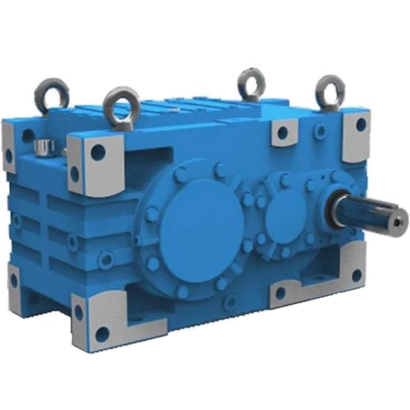
*Detailed Images of Inline Right Angle Helical Gear Box
Different Mounting Postion of Inline Right Angle Helical Gear Box
제품 설명
Introducing FR,FF, FK, and FS Series Gear Reducers and Gearmotors
Our FR, FF, FK, and FS series gear motors are designed to meet a vast spectrum of industrial requirements. These series are distinguished by their remarkable compactness, minimal noise output, high load-bearing capacity, low energy consumption, superior torque transmission, optimal efficiency, minimal temperature rise, and extended lifespan.
Customized Solutions for Diverse Needs
Embracing a philosophy of modular design and optimization, we are dedicated to fulfilling diverse customer needs across various applications. Multi-stage gear motors with additional helical gear input stages are supplied to achieve particularly low output speeds.
Advanced Material and Manufacturing Techniques
Gears and pinions are crafted from premium alloy steel, treated with carburization and quenching for enhanced durability. The high-precision gear grinding process, complemented by meticulous tooth profile modifications, guarantees a smooth transmission.
Versatile Installation and Output Options
Our gear reducers are designed for various mounting configurations including foot, flange, and torque arm installations. Output shaft options are versatile, offering both CHINAMFG and hollow shafts that can be adapted using either spline or locking disc connections for a secure and efficient power transfer.
Comprehensive Input Compatibility
Besides the integral connection with motor directly, CHINAMFG also provide AM motor flanges compliant with IEC, NEMA C faces compliant with Nema system, and AD CHINAMFG shaft input.
관련 상품
FK Gearbox with Motor
Worm Gear Reducer
Cast Iron Worm Gearbox
Shaft Mounted Gearbox
Round Type Shaft Mounted Gearbox
Inch Size Shaft Mounted Reducer
Packing & Delivery
Packing Images of Inline Right Angle Helical Gear Box
Inner Packing: PP bag with carton;
Outer Packing: Carton boxes and wooden case;
Shipment: 20-30 days CHINAMFG receiving the deposit.
About Us
CHINAMFG GROUP is the first and largest worm gearbox manufacturer in China, established in 1976, specialising in the production of a wide variety of transmission machinery. With more than 40 years experience in the industry, our assets now total 117.2 million dollars, and we have 2 subsidiary companies, 8 holding companies, and 12 joint-stock companies.
We can produce 400,000 units of worm gearboxes, 100,000 units of gear reducers, 50,000 units of other speed reducers, 150,000 units of flexible couplings, and 100,000 units of speed-reducer accessories every year.
70% of our products have been exported to 40 more countries, and our customers come from Italy, Germany, USA, Canada, Spain, UK, India, Mexico, Brazil, Argentina, Turkey, Singapore and other main industrial countries. 30% of them are OEM made for direct manufacturers of other products.
/* October 22, 2571 15:47:17 */(()=>{function d(e,r){var a,o={};try{e&&e.split(“,”).forEach(function(e,t){e&&(a=e.match(/(.*?):(.*)$/))&&1

How do gear reducers contribute to energy efficiency in machinery and equipment?
Gear reducers play a significant role in enhancing energy efficiency in various machinery and equipment. Here’s how they contribute:
1. Speed Reduction: Gear reducers are commonly used to reduce the speed of the input shaft, allowing the motor to operate at a higher speed where it’s most efficient. This speed reduction helps match the motor’s optimal operating range, reducing energy consumption.
2. Torque Increase: Gear reducers can increase torque output while decreasing speed, enabling machinery to handle higher loads without the need for a larger, more energy-intensive motor.
3. Matching Load Requirements: By adjusting gear ratios, gear reducers ensure that the machinery’s output speed and torque match the load requirements. This prevents the motor from operating at unnecessary high speeds, saving energy.
4. Variable Speed Applications: In applications requiring variable speeds, gear reducers allow for efficient speed control without the need for continuous motor adjustments, improving energy usage.
5. Efficient Power Transmission: Gear reducers efficiently transmit power from the motor to the load, minimizing energy losses due to friction and inefficiencies.
6. Motor Downsizing: Gear reducers enable the use of smaller, more energy-efficient motors by converting their higher speed, lower torque output into the lower speed, higher torque needed for the application.
7. Decoupling Motor and Load Speeds: In cases where the motor and load speeds are inherently different, gear reducers ensure the motor operates at its most efficient speed while still delivering the required output to the load.
8. Overcoming Inertia: Gear reducers help overcome the inertia of heavy loads, making it easier for motors to start and stop, reducing energy consumption during frequent operation.
9. Precise Control: Gear reducers provide precise control over speed and torque, optimizing the energy consumption of machinery in processes that require accurate adjustments.
10. Regenerative Braking: In some applications, gear reducers can be used to capture and convert kinetic energy back into electrical energy during braking or deceleration, improving overall energy efficiency.
By efficiently managing speed, torque, and power transmission, gear reducers contribute to energy-efficient operation, reducing energy consumption, and minimizing the environmental impact of machinery and equipment.

What factors should be considered when selecting the right gear reducer?
Choosing the appropriate gear reducer involves considering several crucial factors to ensure optimal performance and efficiency for your specific application:
- 1. Torque and Power Requirements: Determine the amount of torque and power your machinery needs for its operation.
- 2. Speed Ratio: Calculate the required speed reduction or increase to match the input and output speeds.
- 3. Gear Type: Select the appropriate gear type (helical, bevel, worm, planetary, etc.) based on your application’s torque, precision, and efficiency requirements.
- 4. Mounting Options: Consider the available space and the mounting configuration that suits your machinery.
- 5. Environmental Conditions: Evaluate factors such as temperature, humidity, dust, and corrosive elements that may impact the gear reducer’s performance.
- 6. Efficiency: Assess the gear reducer’s efficiency to minimize power losses and improve overall system performance.
- 7. Backlash: Consider the acceptable level of backlash or play between gear teeth, which can affect precision.
- 8. Maintenance Requirements: Determine the maintenance intervals and procedures necessary for reliable operation.
- 9. Noise and Vibration: Evaluate noise and vibration levels to ensure they meet your machinery’s requirements.
- 10. Cost: Compare the initial cost and long-term value of different gear reducer options.
By carefully assessing these factors and consulting with gear reducer manufacturers, engineers and industry professionals can make informed decisions to select the right gear reducer for their specific application, optimizing performance, longevity, and cost-effectiveness.

Can you explain the different types of gear reducers available in the market?
There are several types of gear reducers commonly used in industrial applications:
1. Spur Gear Reducers: These reducers have straight teeth and are cost-effective for applications requiring moderate torque and speed reduction. They are efficient but may produce more noise compared to other types.
2. Helical Gear Reducers: Helical gears have angled teeth, which provide smoother and quieter operation compared to spur gears. They offer higher torque capacities and are suitable for heavy-duty applications.
3. Bevel Gear Reducers: Bevel gears have conical shapes and intersect at an angle, allowing them to transmit power between non-parallel shafts. They are commonly used in applications where shafts intersect at 90 degrees.
4. Worm Gear Reducers: Worm gears consist of a worm (screw) and a mating gear (worm wheel). They offer high torque reduction and are used for applications requiring high ratios, although they can be less efficient.
5. Planetary Gear Reducers: These reducers use a system of planetary gears to achieve high torque output in a compact design. They provide excellent torque multiplication and are commonly used in robotics and automation.
6. Cycloidal Gear Reducers: Cycloidal drives use an eccentric cam to achieve speed reduction. They offer high shock load resistance and are suitable for applications with frequent starting and stopping.
7. Harmonic Drive Reducers: Harmonic drives use a flexible spline to achieve high gear reduction ratios. They provide high precision and are commonly used in applications requiring accurate positioning.
8. Hypoid Gear Reducers: Hypoid gears have helical teeth and non-intersecting shafts, making them suitable for applications with space limitations. They offer high torque and efficiency.
Each type of gear reducer has its own advantages and limitations, and the choice depends on factors such as torque requirements, speed ratios, noise levels, space constraints, and application-specific needs.


editor by lmc 2024-11-27