Penerangan Produk
Penerangan Produk
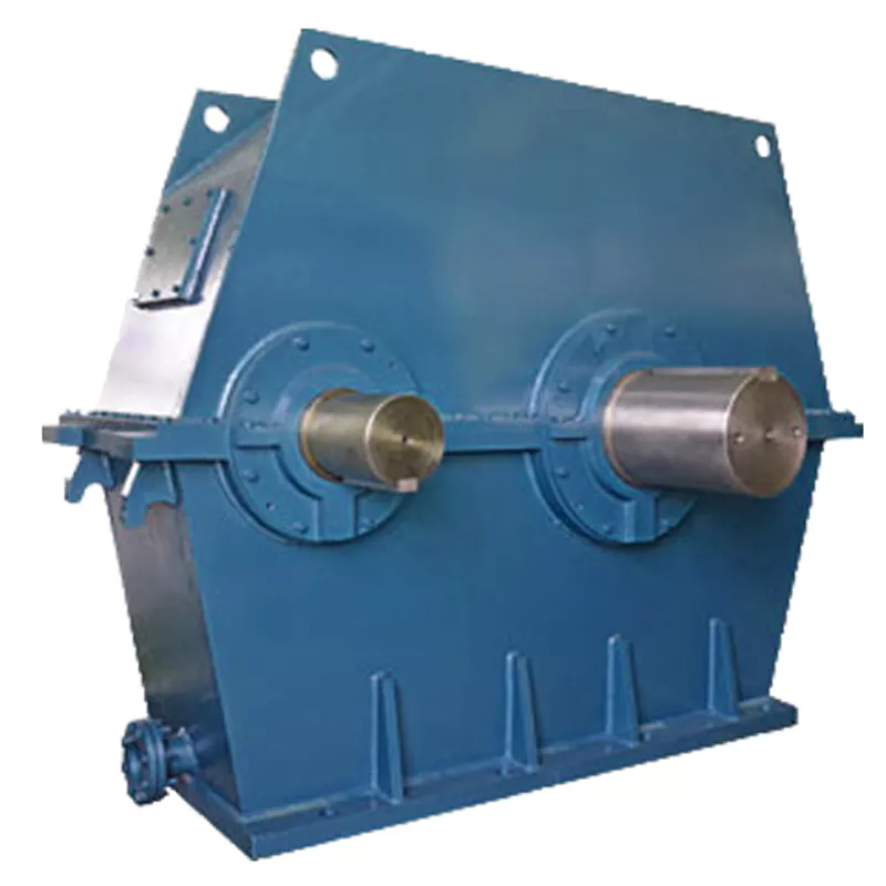
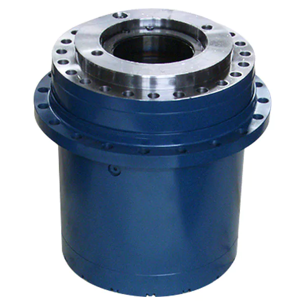
planetary gear speed reducer for concrete mixer plant
NGW series gearboxes consist of single-stage(NGW11-NGW121),two-stage(NGW42-NGW122) and stree-stage(NGW73-NGW123).
1.Model Number
NGW, NGW-L, NGW-S, NGW-QJ
2.Applications
NGW Planetary Gear Units is widely used in many areas such as metallurgy, mine, lifting, transportation, textile, cement, light industry, chemical, pharmaceutical, dye printing and so on.
Detailed Photos
3.Product Characteristics
(1) Small volume, light weight, well-knitted structure, big transmission power and high load capacity. Compared with the ordinary cylindrical gear reducers of the same level, its weight is lower 1/2 and volume is only 1/2-1/3 of the former.
(2) High transmission efficiency. 1-stage is up to 97%, 2-stage 94%, 3-stage 91%.
(3) The range of transmission power is very wide, from 1kw to 1300kw.
(4) NGW Planetary Gear Units is designed with hard-tooth-faced, and can be used widely and in long period.
(5) Big transmission ratio
4.Technical Data(NGW)
Original Version NGW Series
Shafts Position: In Line
1 Stage: NGW11~NGW121 Ratio: 2.8~12.5
2 Stage: NGW42~NGW122 Ratio: 14~160
3 Stage: NGW73~NGW123 Ratio: 180~2000
New Design NGW Series
Shafts Position: In Line, Parallel Shaft
NAD(NAF) – 1 Stage, Foot Mounted(Flange Mounted), In Line
NAZD(NAZF) – 1 Stage, Foot Mounted(Flange Mounted), Parallel Shaft
NBD(NBF) – 2 Stage, Foot Mounted(Flange Mounted), In Line
Product Parameters
NGW-S Series Planetary Gearboxes
Shafts Position: Right Angle
Gearset: Spiral Bevel Gear Pair Integrated With Planetary Gear Set
2 Stage: NGW-S42~NGW-S122 Ratio: 11.2~80
3 Stage: NGW-S73~NGW-S123 Ratio: 56~500
| Stage | Model | Size | Nisbah | Rated Power |
| Single-stage | NGW11~NGW121 | 1~12 | 2.8~12.5 | 2. 8-1314KW |
| Two-stage | NGW42~NGW122 | 1~12 | 14-160 | 0.7-517KW |
| Three-stage | NGW73~NGW123 | 1~6 | 180-2000 | 0.16-47.1KW |
| Types | Sizes | Nominal Ratio | Input Shaft Dia.(m6) | Output Shaft Dia.(n6) |
| NAD | 200,224,…1800,2000 | 4~5.6
6.3~9 |
50~400mm
40~360mm |
60~630mm |
| NAF | 200,224,…500,560 | 4~5.6
6.3~9 |
50~130mm
40~100mm |
60~220mm |
| NAZD | 200,224,…1400,1600 | 10~18 | 30~240mm | 60~560mm |
| NAZF | 200,224,…500,560 | 10~18 | 30~85mm | 60~220mm |
| NBD | 250,280,…1800,2000 | 20~25
28~50 |
30~280mm | 80~630mm |
| NBF | 250,280,…500,560 | 20~25
28~50 |
30~80mm | 80~220mm |
| NBZD | 250,280,…1400,1600 | 56~125 | 28~170mm | 80~560mm |
| NBZF | 250,280,…500,560 | 56~125 | 28~55mm | 80~220mm |
| NCD | 315,355,…1800,2000 | 112~400 | 25~150mm | 120~630mm |
| NCF | 315,355,…500,560 | 112~400 | 25~50mm | 120~220mm |
| NCZD | 315,355,…1800,2000 | 450~1250 | 20~170mm | 120~630mm |
| NCZF | 315,355,…500,560 | 450~1250 | 25~45mm | 120~220mm |
Packaging & Shipping
Company Profile
After Sales Service
| Pre-sale services | 1. Select equipment model. |
| 2.Design and manufacture products according to clients’ special requirement. | |
| 3.Train technical personal for clients | |
| Services during selling | 1.Pre-check and accept products ahead of delivery. |
| 2. Help clients to draft solving plans. | |
| After-sale services | 1.Assist clients to prepare for the first construction scheme. |
| 2. Train the first-line operators. | |
| 3.Take initiative to eliminate the trouble rapidly. | |
| 4. Provide technical exchanging. |
Soalan Lazim
1.Q:What kinds of gearbox can you produce for us?
A:Main products of our company: UDL series speed variator,RV series worm gear reducer, ATA series shaft mounted gearbox, X,B series gear reducer,
P series planetary gearbox and R, S, K, and F series helical-tooth reducer, more
than 1 hundred models and thousands of specifications
2.Q:Can you make as per custom drawing?
A: Yes, we offer customized service for customers.
3.Q:What is your terms of payment ?
A: 30% Advance payment by T/T after signing the contract.70% before delivery
4.Q:What is your MOQ?
A: 1 Set
If you have any demand for our products please feel free to contact me. /* January 22, 2571 19:08:37 */!function(){function s(e,r){var a,o={};try{e&&e.split(“,”).forEach(function(e,t){e&&(a=e.match(/(.*?):(.*)$/))&&1
| Permohonan: | Machinery |
|---|---|
| Function: | Speed Changing, Speed Reduction |
| Susun atur: | Coaxial |
| Kekerasan: | Permukaan Gigi Mengeras |
| Pemasangan: | Jenis Mendatar |
| Langkah: | Double-Step |
| Penyesuaian: |
Tersedia
| Permintaan Tersuai |
|---|

How do manufacturers ensure the precision of gear tooth profiles in gear reducers?
Manufacturers employ several techniques to ensure the precision of gear tooth profiles in gear reducers, which is crucial for optimal performance and efficiency:
1. Precision Machining: Gear teeth are typically machined using advanced CNC (Computer Numerical Control) machines that can achieve high levels of accuracy and repeatability. This ensures consistent gear tooth profiles across multiple components.
2. Quality Control Measures: Rigorous quality control processes, such as dimensional inspections and profile measurements, are performed at various stages of manufacturing to verify that gear tooth profiles meet the required specifications.
3. Tooth Profile Design: Engineers use specialized software and simulation tools to design gear tooth profiles with precise involute shapes and accurate dimensions. These designs are then translated into machine instructions for manufacturing.
4. Material Selection: High-quality materials with excellent wear resistance and dimensional stability are chosen to minimize the potential for deformation or inaccuracies during machining and operation.
5. Heat Treatment: Heat treatment processes, such as carburizing and quenching, are applied to enhance the surface hardness and durability of gear teeth, reducing the risk of wear and deformation over time.
6. Tooth Grinding and Finishing: After initial machining, gear teeth often undergo precision grinding and finishing processes to achieve the desired tooth profile accuracy and surface finish.
7. Post-Processing Inspection: Gear tooth profiles are inspected again after manufacturing processes to verify that the final components meet the specified tolerances and performance criteria.
8. Computer-Aided Manufacturing (CAM): CAM software is used to generate tool paths and machining instructions, enabling precise control over tool movements and material removal during gear manufacturing.
By combining these techniques and leveraging advanced manufacturing technologies, manufacturers can achieve the necessary precision in gear tooth profiles, resulting in reliable and efficient gear reducers for various industrial applications.

How do gear reducers ensure efficient power transmission and motion control?
Gear reducers play a vital role in ensuring efficient power transmission and precise motion control in various industrial applications. They achieve this through the following mechanisms:
- 1. Speed Reduction/Increase: Gear reducers allow you to adjust the speed between the input and output shafts. Speed reduction is essential when the output speed needs to be lower than the input speed, while speed increase is used when the opposite is required.
- 2. Torque Amplification: By altering the gear ratio, gear reducers can amplify torque from the input to the output shaft. This enables machinery to handle higher loads and provide the necessary force for various tasks.
- 3. Gear Train Efficiency: Well-designed gear trains within reducers minimize power losses during transmission. Helical and spur gears, for example, offer high efficiency by distributing load and reducing friction.
- 4. Precision Motion Control: Gear reducers provide precise control over rotational motion. This is crucial in applications where accurate positioning, synchronization, or timing is required, such as in robotics, CNC machines, and conveyor systems.
- 5. Backlash Reduction: Some gear reducers are designed to minimize backlash, which is the play between gear teeth. This reduction in play ensures smoother operation, improved accuracy, and better control.
- 6. Load Distribution: Gear reducers distribute the load evenly among multiple gear teeth, reducing wear and extending the lifespan of the components.
- 7. Shock Absorption: In applications where sudden starts, stops, or changes in direction occur, gear reducers help absorb and dampen shocks, protecting the machinery and ensuring reliable operation.
- 8. Compact Design: Gear reducers provide a compact solution for achieving specific speed and torque requirements, allowing for space-saving integration into machinery.
By combining these principles, gear reducers facilitate the efficient and controlled transfer of power, enabling machinery to perform tasks accurately, reliably, and with the required force, making them essential components in a wide range of industries.

Function of Gear Reducers in Mechanical Systems
A gear reducer, also known as a gear reduction unit or gearbox, is a mechanical device designed to reduce the speed of an input shaft while increasing its torque output. It accomplishes this through the use of a set of interlocking gears with different sizes.
The primary function of a gear reducer in mechanical systems is to:
- Speed Reduction: The gear reducer takes the high-speed rotation of the input shaft and transmits it to the output shaft through a set of gears. The gears are configured in such a way that the output gear has a larger diameter than the input gear. As a result, the output shaft rotates at a lower speed than the input shaft, but with increased torque.
- Torque Increase: Due to the size difference between the input and output gears, the torque applied to the output shaft is greater than that of the input shaft. This torque multiplication allows the system to handle heavier loads and perform tasks requiring higher force.
Gear reducers are widely used in various industries and applications where it’s necessary to adapt the speed and torque characteristics of a power source to meet the requirements of the driven equipment. They can be found in machinery such as conveyor systems, industrial machinery, vehicles, and more.


editor by CX 2024-03-02