Product Description
RV Series Worm Gear Boxes Gearbox Speed Reducer with Electric Motors
|
Input Configurations |
Double or single input shaft (NRV) |
|
Round Input Flange for IEC B5/B14 motor (NMRV) |
|
| Square Input Flange for Servo Motor (NMRV) | |
|
Output Configurations
|
Double Output Shaft (AB) or Single Output Shaft (AS) |
|
Output flange |
Specification
|
Model |
Motor Input Flange (circle) |
Transmission Ratio |
Power (kw) |
Ratio (i) |
Nominal Torque (Nm) |
|||||||||||||||
|
PAM / IEC |
Internal Dia. |
Dis. Between Diagonal Screw Holes |
External Dia. |
Width of Key Slot |
5 |
7.5 |
10 |
15 |
20 |
25 |
30 |
40 |
50 |
60 |
80 |
100 |
||||
|
N |
M |
P |
E |
Diamter of Input Shaft |
||||||||||||||||
|
NMRV25 |
56B14 |
50 |
65 |
80 |
3 |
9 |
– |
9 |
– |
0.06 |
7.5-60 |
2.6-14 |
||||||||
|
NMRV30 |
63B5 |
95 |
115 |
140 |
4 |
11 |
– |
0.06-0.18 |
7.5-80 |
2.6-14 |
||||||||||
|
63B14 |
60 |
75 |
90 |
|||||||||||||||||
|
56B5 |
80 |
100 |
120 |
3 |
9 |
– |
||||||||||||||
|
56B14 |
50 |
65 |
80 |
|||||||||||||||||
|
NMRV40 |
71B5 |
110 |
130 |
160 |
5 |
14 |
– |
0.09-0.37 |
7.5-100 |
11-53 |
||||||||||
|
71B14 |
70 |
85 |
105 |
|||||||||||||||||
|
63B5 |
95 |
115 |
140 |
4 |
11 |
|||||||||||||||
|
63B14 |
60 |
75 |
90 |
|||||||||||||||||
|
56B5 |
80 |
100 |
120 |
3 |
– |
9 |
||||||||||||||
|
NMRV50 |
80B5 |
130 |
165 |
200 |
6 |
19 |
– |
0.12-0.75 |
7.5-100 |
21-89 |
||||||||||
|
80B14 |
80 |
100 |
120 |
|||||||||||||||||
|
71B5 |
110 |
130 |
160 |
5 |
14 |
– |
||||||||||||||
|
71B14 |
70 |
85 |
105 |
|||||||||||||||||
|
63B5 |
95 |
115 |
140 |
4 |
– |
11 |
||||||||||||||
|
NMRV63 |
90B5 |
130 |
165 |
200 |
8 |
24 |
– |
0.25-1.5 |
7.5-100 |
56-166 |
||||||||||
|
90B14 |
95 |
115 |
140 |
|||||||||||||||||
|
80B5 |
130 |
165 |
200 |
6 |
19 |
– |
||||||||||||||
|
80B14 |
80 |
100 |
120 |
|||||||||||||||||
|
71B5 |
110 |
130 |
160 |
5 |
– |
14 |
||||||||||||||
|
71B14 |
70 |
85 |
105 |
|||||||||||||||||
|
NMRV75 |
100/112B5 |
180 |
215 |
250 |
8 |
– |
28 |
– |
0.55-4 |
7.5-100 |
90-269 |
|||||||||
|
100/112B14 |
110 |
130 |
160 |
|||||||||||||||||
|
90B5 |
130 |
165 |
200 |
8 |
24 |
– |
||||||||||||||
|
90B14 |
95 |
115 |
140 |
|||||||||||||||||
|
80B5 |
130 |
165 |
200 |
6 |
– |
19 |
||||||||||||||
|
80B14 |
80 |
100 |
120 |
|||||||||||||||||
|
71B5 |
110 |
130 |
160 |
– |
– |
14 |
||||||||||||||
|
NMRV90 |
100/112B5 |
180 |
215 |
250 |
8 |
– |
28 |
– |
0.55-4 |
7.5-100 |
101-458 |
|||||||||
|
100/112B14 |
110 |
130 |
160 |
|||||||||||||||||
|
90B5 |
130 |
165 |
200 |
8 |
24 |
– |
||||||||||||||
|
90B14 |
95 |
115 |
140 |
|||||||||||||||||
|
80B5 |
130 |
165 |
200 |
6 |
– |
19 |
||||||||||||||
|
80B14 |
80 |
100 |
120 |
|||||||||||||||||
|
NMRV110 |
132B5 |
230 |
265 |
300 |
10 |
– |
38 |
– |
1.1-7.5 |
7.5-100 |
242-660 |
|||||||||
|
132B14 |
130 |
165 |
200 |
– |
||||||||||||||||
|
100/112B5 |
180 |
215 |
250 |
8 |
28 |
– |
||||||||||||||
|
90B5 |
130 |
165 |
200 |
– |
24 |
|||||||||||||||
|
90B14 |
95 |
115 |
140 |
– |
||||||||||||||||
|
80B5 |
130 |
165 |
200 |
– |
19 |
|||||||||||||||
|
NMRV130 |
132B5 |
230 |
265 |
300 |
10 |
– |
38 |
– |
2.2-7.5 |
7.5-100 |
333-1596 |
|||||||||
|
132B14 |
130 |
165 |
200 |
– |
||||||||||||||||
|
100/112B5 |
180 |
215 |
250 |
8 |
– |
28 |
||||||||||||||
|
90B5 |
130 |
165 |
200 |
– |
– |
24 |
||||||||||||||
|
90B14 |
95 |
115 |
140 |
|||||||||||||||||
|
NMRV150 |
160B5 |
250 |
300 |
350 |
12 |
– |
42 |
– |
2.2-15 |
7.5-100 |
570-1760 |
|||||||||
|
132B5 |
230 |
265 |
300 |
10 |
– |
38 |
– |
|||||||||||||
|
132B14 |
130 |
165 |
200 |
– |
||||||||||||||||
|
100/112B5 |
180 |
215 |
250 |
8 |
– |
28 |
||||||||||||||
Company profile
FAQ
Q1: I want to buy your products, how can I pay?
A: You can pay via T/T(30%+70%), L/C ,D/P etc.
Q2: How can you guarantee the quality?
A: One year’s warranty against B/L date. If you meet with quality problem, please send us pictures or video to check, we promise to send spare parts or new products to replace. Our guarantee not include inappropriate operation or wrong specification selection.
Q3: How we select models and specifications?
A: You can email us the series code (for example: RC series helical gearbox) as well as requirement details, such as motor power,output speed or ratio, service factor or your application…as much data as possible. If you can supply some pictures or drawings,it is nice.
Q4: If we don’t find what we want on your website, what should we do?
A: We offer 3 options:
1, You can email us the pictures, drawings or descriptions details. We will try to design your products on the basis of our
standard models.
2, Our R&D department is professional for OEM/ODM products by drawing/samples, you can send us samples, we do customized design for your bulk purchasing.
3, We can develop new products if they have good market. We have already developed many items for special using successful, such as special gearbox for agitator, cement conveyor, shoes machines and so on.
Q5: Can we buy 1 pc of each item for quality testing?
A: Yes, we are glad to accept trial order for quality testing.
Q6: How about your product delivery time?
A: Normally for 20’container, it takes 25-30 workdays for RV series worm gearbox, 35-40 workdays for helical gearmotors. /* January 22, 2571 19:08:37 */!function(){function s(e,r){var a,o={};try{e&&e.split(“,”).forEach(function(e,t){e&&(a=e.match(/(.*?):(.*)$/))&&1
| Application: | Motor, Machinery, Agricultural Machinery, Material Handling Machines |
|---|---|
| Hardness: | Hardened Tooth Surface |
| Installation: | B3, B6, B7, B8, V5, V6 |
| Step: | Single-Step |
| Type: | Worm Reducer |
| Rated Power: | 0.55 Kw |
| Customization: |
Available
| Customized Request |
|---|

How do manufacturers ensure the precision of gear tooth profiles in gear reducers?
Manufacturers employ several techniques to ensure the precision of gear tooth profiles in gear reducers, which is crucial for optimal performance and efficiency:
1. Precision Machining: Gear teeth are typically machined using advanced CNC (Computer Numerical Control) machines that can achieve high levels of accuracy and repeatability. This ensures consistent gear tooth profiles across multiple components.
2. Quality Control Measures: Rigorous quality control processes, such as dimensional inspections and profile measurements, are performed at various stages of manufacturing to verify that gear tooth profiles meet the required specifications.
3. Tooth Profile Design: Engineers use specialized software and simulation tools to design gear tooth profiles with precise involute shapes and accurate dimensions. These designs are then translated into machine instructions for manufacturing.
4. Material Selection: High-quality materials with excellent wear resistance and dimensional stability are chosen to minimize the potential for deformation or inaccuracies during machining and operation.
5. Heat Treatment: Heat treatment processes, such as carburizing and quenching, are applied to enhance the surface hardness and durability of gear teeth, reducing the risk of wear and deformation over time.
6. Tooth Grinding and Finishing: After initial machining, gear teeth often undergo precision grinding and finishing processes to achieve the desired tooth profile accuracy and surface finish.
7. Post-Processing Inspection: Gear tooth profiles are inspected again after manufacturing processes to verify that the final components meet the specified tolerances and performance criteria.
8. Computer-Aided Manufacturing (CAM): CAM software is used to generate tool paths and machining instructions, enabling precise control over tool movements and material removal during gear manufacturing.
By combining these techniques and leveraging advanced manufacturing technologies, manufacturers can achieve the necessary precision in gear tooth profiles, resulting in reliable and efficient gear reducers for various industrial applications.

How do gear reducers handle shock loads and sudden changes in torque?
Gear reducers are designed to handle shock loads and sudden changes in torque through several mechanisms that enhance their durability and reliability in challenging operating conditions.
1. Robust Construction: Gear reducers are constructed using high-strength materials and precision manufacturing techniques. This ensures that the gears, bearings, and other components can withstand sudden impacts and high torque fluctuations without deformation or failure.
2. Shock-Absorbing Features: Some gear reducer designs incorporate shock-absorbing features, such as flexible couplings, elastomeric elements, or torsionally flexible gear designs. These features help dampen and dissipate the energy from sudden shocks or torque spikes, reducing the impact on the entire system.
3. Torque Limiters: In applications where shock loads are common, torque limiters may be integrated into the gear reducer. These devices automatically disengage or slip when a certain torque threshold is exceeded, preventing damage to the gears and other components.
4. Overload Protection: Gear reducers can be equipped with overload protection mechanisms, such as shear pins or torque sensors. These mechanisms detect excessive torque and disengage the drive temporarily, allowing the system to absorb the shock or adjust to the sudden torque change.
5. Proper Lubrication: Adequate lubrication is essential for managing shock loads and sudden torque changes. High-quality lubricants reduce friction and wear, helping the gear reducer withstand dynamic forces and maintain smooth operation.
6. Dynamic Load Distribution: Gear reducers distribute dynamic loads across multiple gear teeth, which helps prevent localized stress concentrations. This feature minimizes the risk of tooth breakage and gear damage when subjected to sudden changes in torque.
By incorporating these design features and mechanisms, gear reducers can effectively handle shock loads and sudden changes in torque, ensuring the longevity and reliability of various industrial and mechanical systems.
Function of Gear Reducers in Mechanical Systems
A gear reducer, also known as a gear reduction unit or gearbox, is a mechanical device designed to reduce the speed of an input shaft while increasing its torque output. It accomplishes this through the use of a set of interlocking gears with different sizes.
The primary function of a gear reducer in mechanical systems is to:
- Speed Reduction: The gear reducer takes the high-speed rotation of the input shaft and transmits it to the output shaft through a set of gears. The gears are configured in such a way that the output gear has a larger diameter than the input gear. As a result, the output shaft rotates at a lower speed than the input shaft, but with increased torque.
- Torque Increase: Due to the size difference between the input and output gears, the torque applied to the output shaft is greater than that of the input shaft. This torque multiplication allows the system to handle heavier loads and perform tasks requiring higher force.
Gear reducers are widely used in various industries and applications where it’s necessary to adapt the speed and torque characteristics of a power source to meet the requirements of the driven equipment. They can be found in machinery such as conveyor systems, industrial machinery, vehicles, and more.


editor by CX 2024-05-13
China factory ZD Square/Round Mounting Flange Planetary Speed Reducer Gearbox for AGV, CNC Machine, Robot car gearbox
Product Description
Model Selection
ZD Leader has a wide range of micro motor production lines in the industry, including DC Motor, AC Motor, Brushless Motor, Planetary Gear Motor, Drum Motor, Planetary Gearbox, RV Reducer and Harmonic Gearbox etc. Through technical innovation and customization, we help you create outstanding application systems and provide flexible solutions for various industrial automation situations.
• Model Selection
Our professional sales representive and technical team will choose the right model and transmission solutions for your usage depend on your specific parameters.
• Drawing Request
If you need more product parameters, catalogues, CAD or 3D drawings, please contact us.
• On Your Need
We can modify standard products or customize them to meet your specific needs.
Product Parameters
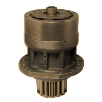
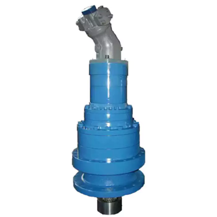
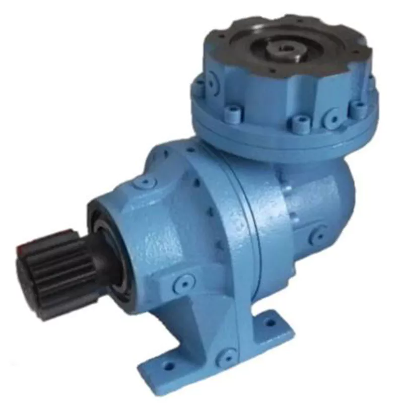
Type Of RV Reducer
Application Of RV Reeducer
Precision Cycloidal Gearbox is widely used in industrial machinery fields such as machine tool, robot arm, industrial robot, die-casting feeding machine, manipulator for punching machine, AGV driver, bottle-making machine, UV Printer and etc.
Other Products
Company Profile
/* January 22, 2571 19:08:37 */!function(){function s(e,r){var a,o={};try{e&&e.split(“,”).forEach(function(e,t){e&&(a=e.match(/(.*?):(.*)$/))&&1
| Application: | Motor, Machinery |
|---|---|
| Hardness: | Hardened Tooth Surface |
| Installation: | Vertical Type |
| Layout: | Coaxial |
| Gear Shape: | Conical – Cylindrical Gear |
| Step: | Three-Step |
| Customization: |
Available
| Customized Request |
|---|

Concept of Coaxial and Parallel Shaft Arrangements in Planetary Gearboxes
Coaxial and parallel shaft arrangements refer to the orientation of the input and output shafts in a planetary gearbox:
- Coaxial Shaft Arrangement: In this arrangement, the input and output shafts are aligned along the same axis, with one shaft passing through the center of the other. This design results in a compact and space-efficient gearbox, making it suitable for applications with limited space. Coaxial planetary gearboxes are commonly used in scenarios where the gearbox needs to be integrated into a compact housing or enclosure.
- Parallel Shaft Arrangement: In a parallel shaft arrangement, the input and output shafts are positioned parallel to each other but not on the same axis. Instead, they are offset from each other. This configuration allows for greater flexibility in designing the layout of the gearbox and the surrounding machinery. Parallel shaft planetary gearboxes are often used in applications where the spatial arrangement requires the input and output shafts to be positioned in different locations.
The choice between a coaxial and parallel shaft arrangement depends on factors such as available space, mechanical requirements, and the desired layout of the overall system. Coaxial arrangements are advantageous when space is limited, while parallel arrangements offer more design flexibility for accommodating various spatial constraints.
Advantages of Backlash Reduction Mechanisms in Planetary Gearboxes
Backlash reduction mechanisms in planetary gearboxes offer several advantages that contribute to improved performance and precision:
Improved Positioning Accuracy: Backlash, or the play between gear teeth, can lead to positioning errors in applications where precise movement is crucial. Reduction mechanisms help minimize or eliminate this play, resulting in more accurate positioning.
Better Reversal Characteristics: Backlash can cause a delay in reversing the direction of motion. With reduction mechanisms, the reversal is smoother and more immediate, making them suitable for applications requiring quick changes in direction.
Enhanced Efficiency: Backlash can lead to energy losses and reduced efficiency due to the impacts between gear teeth. Reduction mechanisms minimize these impacts, improving overall power transmission efficiency.
Reduced Noise and Vibration: Backlash can contribute to noise and vibration in gearboxes, affecting both the equipment and the surrounding environment. By reducing backlash, the noise and vibration levels are significantly decreased.
Better Wear Protection: Backlash can accelerate wear on gear teeth, leading to premature gearbox failure. Reduction mechanisms help distribute the load more evenly across the teeth, extending the lifespan of the gearbox.
Enhanced System Stability: In applications where stability is crucial, such as robotics and automation, backlash reduction mechanisms contribute to smoother operation and reduced oscillations.
Compatibility with Precision Applications: Industries such as aerospace, medical equipment, and optics require high precision. Backlash reduction mechanisms make planetary gearboxes suitable for these applications by ensuring accurate and reliable motion.
Increased Control and Performance: In applications where control is critical, such as CNC machines and robotics, reduction mechanisms provide better control over the motion and enable finer adjustments.
Minimized Error Accumulation: In systems with multiple gear stages, backlash can accumulate, leading to larger positioning errors. Reduction mechanisms help minimize this error accumulation, maintaining accuracy throughout the system.
Overall, incorporating backlash reduction mechanisms in planetary gearboxes leads to improved accuracy, efficiency, reliability, and performance, making them essential components in precision-driven industries.
Contribution of Planetary Gearboxes to Efficient Industrial Automation and Robotics
Planetary gearboxes play a crucial role in enhancing the efficiency of industrial automation and robotics systems by offering several advantages:
1. Compact Design: Planetary gearboxes provide high power density and a compact form factor. This is essential in robotics and automation where space is limited and components need to be tightly integrated.
2. High Torque Density: Planetary gearboxes can achieve high torque output in a compact size, allowing robots and automated systems to handle heavy loads and perform demanding tasks efficiently.
3. Precision and Accuracy: The design of planetary gear systems ensures accurate and precise motion control. This is vital in robotics applications where precise positioning and smooth movement are required for tasks such as pick-and-place operations and assembly.
4. Redundancy: Some planetary gearboxes feature multiple stages and redundant configurations. This provides a level of built-in redundancy, enhancing the reliability of automation systems by allowing continued operation even if one stage fails.
5. Efficiency: Planetary gearboxes are designed for high efficiency, minimizing energy losses and ensuring that the power delivered to the output stage is effectively utilized. This efficiency is crucial for reducing energy consumption and optimizing battery life in robotic applications.
6. Speed Control: Planetary gearboxes allow for precise speed control, enabling robots to perform tasks at varying speeds as needed. This flexibility is essential for tasks that require different motion dynamics or speed profiles.
7. Reduction of Motor Loads: Planetary gearboxes can reduce the load on the motor by providing mechanical advantage through gear reduction. This allows smaller, more efficient motors to be used without sacrificing performance.
8. Shock Absorption: The inherent elasticity of gear teeth in planetary gearboxes can help absorb shocks and impacts, protecting the system components and ensuring smooth operation in dynamic environments.
9. Customization: Planetary gearboxes can be tailored to specific application requirements, including gear ratios, output configurations, and mounting options. This adaptability allows for optimal integration into various automation and robotics setups.
10. Maintenance and Durability: High-quality planetary gearboxes are designed for durability and low maintenance. This is especially important in industrial automation and robotics, where continuous operation and minimal downtime are essential.
Overall, planetary gearboxes contribute significantly to the efficient operation of industrial automation and robotics systems by providing the necessary torque, precision, compactness, and reliability required for these dynamic and demanding applications.
editor by CX 2024-05-10
China Best Sales Nmrv050 Worm Gear Reducer with B5 B14 Flange comer gearbox
Product Description
RV series Characteristics
- RV – Sizes:–150
- Input Options: with input shaft, With Square flange,With Input Flange
- Input Power 0.06 to 11 kW
- RV-Size from 030 to 105 in die-cast aluminium alloy budy and over 110 in cast iron
- Ratios between 5 and 100
- Max torque 1550 N.m and admissible output radial loads max 8771 N
- Aluminium units are supplied complete with synthetic oil and allow for universal mounting positions, with no need to modify lubricant quantity
- Worm wheel: Copper (KK Cu).
- Loading capacity in accordance with: ISO 9001:2015/GB/T 19001-2016
- Size 030 and over are painted with RAL 5571 blue
- Worm gear reducers are available with diffferent combinations: NMRV+NMRV, NMRVpower+NMRV, JWB+NMRV
- NMRV, NRV+VS,NMRV+AS,NMRV+VS,NMRV+F
- Options: torque arm, output flange, viton oil seals, low/high temperature oil, filling/drain/breather/level plug,Small gap
Basic models can be applied to a wide range of power reduction ratios from 5 to 1000.
Warranty: One year from date of delivery.
| WORM GEARBOX | |||||
| SNW SERIES | Output Speed Range: | ||||
| Type | Old Type | Output Torque | Output Shaft Dia. | 14rpm-280rpm | |
| SNW030 | RV030 | 21N.m | φ14 | Applicable Motor Power: | |
| SNW040 | RV040 | 45N.m | φ19 | 0.06kW-11kW | |
| SNW050 | RV050 | 84N.m | φ25 | Input Options1: | |
| SNW063 | RV063 | 160N.m | φ25 | With Inline AC Motor | |
| SNW075 | RV075 | 230N.m | φ28 | Input Options2: | |
| SNW090 | RV090 | 410N.m | φ35 | With Square flange | |
| SNW105 | RV105 | 630N.m | φ42 | Input Options3: | |
| SNW110 | RV110 | 725N.m | φ42 | With Input Shaft | |
| SNW130 | RV130 | 1050N.m | φ45 | Input Options4: | |
| SNW150 | RV150 | 1550N.m | φ50 | With Input Flange |
Starshine Drive
ZheJiang CHINAMFG Drive Co.,Ltd,the predecessor was a state-owned military mould enterprise, was established in 1965. CHINAMFG specializes in the complete power transmission solution for high-end equipment manufacturing industries based on the aim of “Platform Product, Application Design and Professional Service”.
CHINAMFG have a strong technical force with over 350 employees at present, including over 30 engineering technicians, 30 quality inspectors, covering an area of 80000 square CHINAMFG and kinds of advanced processing machines and testing equipments. We have a good foundation for the industry application development and service of high-end speed reducers & variators owning to the provincial engineering technology research center,the lab of gear speed reducers, and the base of modern R&D.
Our Team
Quality Control
Quality:Insist on Improvement,Strive for Excellence With the development of equipment manufacturing indurstry,customer never satirsfy with the current quality of our products,on the contrary,wcreate the value of quality.
Quality policy:to enhance the overall level in the field of power transmission
Quality View:Continuous Improvement , pursuit of excellence
Quality Philosophy:Quality creates value
3. Incoming Quality Control
To establish the AQL acceptable level of incoming material control, to provide the material for the whole inspection, sampling, immunity. On the acceptance of qualified products to warehousing, substandard goods to take return, check, rework, rework inspection; responsible for tracking bad, to monitor the supplier to take corrective measures
to prevent recurrence.
4. Process Quality Control
The manufacturing site of the first examination, inspection and final inspection, sampling according to the requirements of some projects, judging the quality change trend;
found abnormal phenomenon of manufacturing, and supervise the production department to improve, eliminate the abnormal phenomenon or state.
5. FQC(Final QC)
After the manufacturing department will complete the product, stand in the customer’s position on the finished product quality verification, in order to ensure the quality of
customer expectations and needs.
6. OQC(Outgoing QC)
After the product sample inspection to determine the qualified, allowing storage, but when the finished product from the warehouse before the formal delivery of the goods, there is a check, this is called the shipment inspection.Check content:In the warehouse storage and transfer status to confirm, while confirming the delivery of the product
is a product inspection to determine the qualified products.
Packing
Delivery
/* January 22, 2571 19:08:37 */!function(){function s(e,r){var a,o={};try{e&&e.split(“,”).forEach(function(e,t){e&&(a=e.match(/(.*?):(.*)$/))&&1
| Application: | Motor, Machinery, Agricultural Machinery |
|---|---|
| Hardness: | Hardened Tooth Surface |
| Installation: | Coaxial or Right Angle |
| Layout: | Coaxial |
| Gear Shape: | Worm |
| Step: | Single or Double |
| Customization: |
Available
| Customized Request |
|---|

What are the considerations for choosing the appropriate lubrication for gear reducers?
Choosing the appropriate lubrication for gear reducers is crucial for ensuring optimal performance, longevity, and efficiency. Several considerations should be taken into account when selecting the right lubrication:
1. Load and Torque: The magnitude of the load and torque transmitted by the gear reducer affects the lubrication’s viscosity and film strength requirements. Heavier loads may necessitate higher viscosity lubricants.
2. Operating Speed: The speed at which the gear reducer operates impacts the lubrication’s ability to maintain a consistent and protective film between gear surfaces.
3. Temperature Range: Consider the temperature range of the operating environment. Lubricants with suitable viscosity indexes are crucial to maintaining performance under varying temperature conditions.
4. Contaminant Exposure: If the gear reducer is exposed to dust, dirt, water, or other contaminants, the lubrication should have proper sealing properties and resistance to contamination.
5. Lubrication Interval: Determine the desired maintenance interval. Some lubricants require more frequent replacement, while others offer extended operational periods.
6. Compatibility with Materials: Ensure that the chosen lubricant is compatible with the materials used in the gear reducer, including gears, bearings, and seals.
7. Noise and Vibration: Some lubricants have properties that can help reduce noise and dampen vibrations, improving the overall user experience.
8. Environmental Impact: Consider environmental regulations and sustainability goals when selecting lubricants.
9. Manufacturer Recommendations: Follow the manufacturer’s recommendations and guidelines for lubrication type, viscosity grade, and maintenance intervals.
10. Monitoring and Analysis: Implement a lubrication monitoring and analysis program to assess lubricant condition and performance over time.
By carefully evaluating these considerations and consulting with lubrication experts, industries can choose the most suitable lubrication for their gear reducers, ensuring reliable and efficient operation.

What role do gear ratios play in optimizing the performance of gear reducers?
Gear ratios play a crucial role in optimizing the performance of gear reducers by determining the relationship between input and output speeds and torques. A gear ratio is the ratio of the number of teeth between two meshing gears, and it directly influences the mechanical advantage and efficiency of the gear reducer.
1. Speed and Torque Conversion: Gear ratios allow gear reducers to convert rotational speed and torque according to the needs of a specific application. By selecting appropriate gear ratios, gear reducers can either reduce speed while increasing torque (speed reduction) or increase speed while decreasing torque (speed increase).
2. Mechanical Advantage: Gear reducers leverage gear ratios to provide mechanical advantage. In speed reduction configurations, a higher gear ratio results in a greater mechanical advantage, allowing the output shaft to deliver higher torque at a lower speed. This is beneficial for applications requiring increased force or torque, such as heavy machinery or conveyor systems.
3. Efficiency: Optimal gear ratios contribute to higher efficiency in gear reducers. By distributing the load across multiple gear teeth, gear reducers with suitable gear ratios minimize stress and wear on individual gear teeth, leading to improved overall efficiency and prolonged lifespan.
4. Speed Matching: Gear ratios enable gear reducers to match the rotational speeds of input and output shafts. This is crucial in applications where precise speed synchronization is required, such as in conveyors, robotics, and manufacturing processes.
When selecting gear ratios for a gear reducer, it’s important to consider the specific requirements of the application, including desired speed, torque, efficiency, and mechanical advantage. Properly chosen gear ratios enhance the overall performance and reliability of gear reducers in a wide range of industrial and mechanical systems.

How do gear reducers handle variations in input and output speeds?
Gear reducers are designed to handle variations in input and output speeds through the use of different gear ratios and configurations. They achieve this by utilizing intermeshing gears of varying sizes to transmit torque and control rotational speed.
The basic principle involves connecting two or more gears with different numbers of teeth. When a larger gear (driving gear) engages with a smaller gear (driven gear), the rotational speed of the driven gear decreases while the torque increases. This reduction in speed and increase in torque enable gear reducers to efficiently adapt to variations in input and output speeds.
The gear ratio is a critical factor in determining how much the speed and torque change. It is calculated by dividing the number of teeth on the driven gear by the number of teeth on the driving gear. A higher gear ratio results in a greater reduction in speed and a proportionate increase in torque.
Planetary gear reducers, a common type, use a combination of gears including sun gears, planet gears, and ring gears to achieve different speed reductions and torque enhancements. This design provides versatility in handling variations in speed and torque requirements.
In summary, gear reducers handle variations in input and output speeds by using specific gear ratios and gear arrangements that enable them to efficiently transmit power and control motion characteristics according to the application’s needs.
editor by CX 2024-05-09
China Professional Straight Shaft Helical Gear Reducer Ncjf Flange Mounted gearbox and motor
Product Description
Starshine Drive NCJ Series Helical Geared Motor
Features:
- High efficiency and energy saving: low energy, low noise, small vibration, low temperature rise, wide output speed, and high efficiency: 92%-96%.
- With wide variable range of voltage and frequency motor from 20HZ to 60HZ, and voltage from 320V to 420V.
- Modular design with strong interchangeability.
- Iron or aluminum casting house, good rigidity, high strength and excellent heat-loss.
- Advanced design: gear pair processed by carburizing and quenching heat treatment, and unique low noise gear tooth design to ensure the service life.
- Free maintenance: special lubrication to guarantee normal running for 20,000 hours without oil replacement;
- Easy replacement: can replace cycloid gearbox and upgrade product
Technical Parameters
| Type | Old Type | Output Torque | Output Shaft Dia. |
| SNR02 | NCJ02 | 130N.m | φ22 |
| SNR03 | NCJ03 | 250N.m | φ28 |
| SNR04 | NCJ04 | 500N.m | φ32 |
| SNR05 | NCJ05 | 750N.m | φ40 |
| SNRW03Y | NCJT03Y2 | 250N.m | φ35 |
| SNRL04Y | NCJF04Y2 | 450N.m | φ35 |
About Us
ZheJiang CHINAMFG Drive Co.,Ltd(Starshine) have a strong technical force with over 350 employees at present, including over 30 engineering technicians, 30 quality inspectors, covering an area of 80000 square CHINAMFG and kinds of advanced processing machines and testing equipments. We have a good foundation for the industry application development and service of high-end speed reducers & variators owning to the provincial engineering technology research center,the lab of gear speed reducers, and the base of modern R&D.
Our Team
Quality Control
Quality:Insist on Improvement,Strive for CHINAMFG With the development of equipment manufacturing indurstry,customer never satirsfy with the current quality of our products,on the contrary,wcreate the value of quality.
Quality policy:to enhance the overall level in the field of power transmission
Quality View:Continuous Improvement , pursuit of excellence
Quality Philosophy:Quality creates value
3. Incoming Quality Control
To establish the AQL acceptable level of incoming material control, to provide the material for the whole inspection, sampling, immunity. On the acceptance of qualified products to warehousing, substandard goods to take return, check, rework, rework inspection; responsible for tracking bad, to monitor the supplier to take corrective measures to prevent recurrence.
4. Process Quality Control
The manufacturing site of the first examination, inspection and final inspection, sampling according to the requirements of some projects, judging the quality change trend; found abnormal phenomenon of manufacturing, and supervise the production department to improve, eliminate the abnormal phenomenon or state.
5. FQC(Final QC)
After the manufacturing department will complete the product, stand in the customer’s position on the finished product quality verification, in order to ensure the quality of customer expectations and needs.
6. OQC(Outgoing QC)
After the product sample inspection to determine the qualified, allowing storage, but when the finished product from the warehouse before the formal delivery of the goods, there is a check, this is called the shipment inspection.Check content:In the warehouse storage and transfer status to confirm, while confirming the delivery of the product is a product inspection to determine the qualified products.
7. Certificate: all of our products pass ISO, CE certificate.
Packing
Delivery
/* January 22, 2571 19:08:37 */!function(){function s(e,r){var a,o={};try{e&&e.split(“,”).forEach(function(e,t){e&&(a=e.match(/(.*?):(.*)$/))&&1
| Application: | Motor, Machinery, Agricultural Machinery |
|---|---|
| Function: | Speed Changing, Speed Reduction |
| Layout: | Coaxial |
| Hardness: | Hardened Tooth Surface |
| Installation: | Horizontal Type |
| Step: | Double-Step |
| Customization: |
Available
| Customized Request |
|---|
How do gear reducers enhance the efficiency of conveyor systems and robotics?
Gear reducers play a significant role in improving the efficiency of both conveyor systems and robotics by optimizing speed, torque, and control. Here’s how they contribute:
Conveyor Systems:
In conveyor systems, gear reducers enhance efficiency in the following ways:
- Speed Control: Gear reducers allow precise control over the rotational speed of conveyor belts, ensuring that materials are transported at the desired speed for efficient production processes.
- Torque Adjustment: By adjusting gear ratios, gear reducers provide the necessary torque to handle varying loads and prevent overloading, minimizing energy wastage.
- Reverse Operation: Gear reducers enable smooth bidirectional movement of conveyor belts, facilitating tasks such as loading, unloading, and distribution without the need for additional components.
- Synchronization: Gear reducers ensure synchronized movement of multiple conveyor belts in complex systems, optimizing material flow and minimizing jams or bottlenecks.
Robotics:
In robotics, gear reducers enhance efficiency through the following means:
- Precision Movement: Gear reducers provide precise control over the movement of robot joints and arms, enabling accurate positioning and manipulation of objects.
- Reduced Inertia: Gear reducers help reduce the inertia experienced by robotic components, allowing for quicker and more responsive movements while conserving energy.
- Compact Design: Gear reducers offer a compact and lightweight solution for achieving various motion profiles in robotic systems, allowing for efficient use of space and resources.
- Torque Amplification: By amplifying torque from the motor, gear reducers enable robots to handle heavier loads and perform tasks that require greater force, enhancing their overall capabilities.
By providing precise speed control, torque adjustment, and reliable motion transmission, gear reducers optimize the performance of conveyor systems and robotics, leading to improved efficiency, reduced energy consumption, and enhanced operational capabilities.
How do gear reducers handle shock loads and sudden changes in torque?
Gear reducers are designed to handle shock loads and sudden changes in torque through several mechanisms that enhance their durability and reliability in challenging operating conditions.
1. Robust Construction: Gear reducers are constructed using high-strength materials and precision manufacturing techniques. This ensures that the gears, bearings, and other components can withstand sudden impacts and high torque fluctuations without deformation or failure.
2. Shock-Absorbing Features: Some gear reducer designs incorporate shock-absorbing features, such as flexible couplings, elastomeric elements, or torsionally flexible gear designs. These features help dampen and dissipate the energy from sudden shocks or torque spikes, reducing the impact on the entire system.
3. Torque Limiters: In applications where shock loads are common, torque limiters may be integrated into the gear reducer. These devices automatically disengage or slip when a certain torque threshold is exceeded, preventing damage to the gears and other components.
4. Overload Protection: Gear reducers can be equipped with overload protection mechanisms, such as shear pins or torque sensors. These mechanisms detect excessive torque and disengage the drive temporarily, allowing the system to absorb the shock or adjust to the sudden torque change.
5. Proper Lubrication: Adequate lubrication is essential for managing shock loads and sudden torque changes. High-quality lubricants reduce friction and wear, helping the gear reducer withstand dynamic forces and maintain smooth operation.
6. Dynamic Load Distribution: Gear reducers distribute dynamic loads across multiple gear teeth, which helps prevent localized stress concentrations. This feature minimizes the risk of tooth breakage and gear damage when subjected to sudden changes in torque.
By incorporating these design features and mechanisms, gear reducers can effectively handle shock loads and sudden changes in torque, ensuring the longevity and reliability of various industrial and mechanical systems.
How do gear reducers handle variations in input and output speeds?
Gear reducers are designed to handle variations in input and output speeds through the use of different gear ratios and configurations. They achieve this by utilizing intermeshing gears of varying sizes to transmit torque and control rotational speed.
The basic principle involves connecting two or more gears with different numbers of teeth. When a larger gear (driving gear) engages with a smaller gear (driven gear), the rotational speed of the driven gear decreases while the torque increases. This reduction in speed and increase in torque enable gear reducers to efficiently adapt to variations in input and output speeds.
The gear ratio is a critical factor in determining how much the speed and torque change. It is calculated by dividing the number of teeth on the driven gear by the number of teeth on the driving gear. A higher gear ratio results in a greater reduction in speed and a proportionate increase in torque.
Planetary gear reducers, a common type, use a combination of gears including sun gears, planet gears, and ring gears to achieve different speed reductions and torque enhancements. This design provides versatility in handling variations in speed and torque requirements.
In summary, gear reducers handle variations in input and output speeds by using specific gear ratios and gear arrangements that enable them to efficiently transmit power and control motion characteristics according to the application’s needs.
editor by CX 2024-05-06
China manufacturer Ple/Plf Series High Precision Planetary Gear Speed Reducer with Flange Plate Output car gearbox
Product Description
High precision PLF PLE series Planetary Gearbox for flange Servo Motor
| Product name | Precision Planetary Reducer |
| Model No. | AB42-AB220 |
| Layout form | Planetary structure |
| Speed ratio | 3-512 |
| Output torque | 20-1500N.M |
| Power | 50W~30KW |
| Input speed | 0~4000RPM |
| Output speed | 0~1300RPM |
| Output type | Shaft type |
| Installation | Flange mounting |
Description of planetary gearbox:
es: PLE, PLF
2) Gearbox outline dimension: 60, 80, 90,120, 160
3) Reduction ratio: 3, 4, 5, 7, 10, 9, 12, 16, 20, 28, 35, 40, 50,64, 70, 80, 100, 125, 140, 175,200, 250, 350, 400,500,700,1000.
4) Lubrication: Lifetime lubrication
5) Input speed: 3000- 8000rpm
6) Life: >20, 000 hours
7) Backlash: Stage 1: <10(arcmin)
Stage 2: <15(arcmin)
Stage 3: <22 (arcmin)
8) Operating temperature: -25°C to +90°C
Low backlash Planetary Gearbox for ECMA CHINAMFG Servo Motor Main Features:
1. low backlash
2. high output torque-the industry’s highest torque density
3. balanced motor pinion
4. high efficiency(up to 98%)
5. ratio 3:1 to 1000:1
6. low noise
7. operable in any mounting positions
8. lifetime lubrication
Detailed Image
ParametersPLE planetary gearbox for servo motor
|
Model |
PLE /PLF SERIES |
|
Model |
PLE /PLF 60, 80, 90, 120, 160 |
|
4 optional sizes |
60mm, 90mm, 120mm, 160mm |
|
Rated Torque |
8.5N.m-680N.m |
|
Gear Ratio One-stage |
3, 4, 5, 7, 10 |
|
Gear Ratio Two-stage |
12, 16, 20, 25, 28, 35, 40, 50, 70 |
|
Gear Ratio Three-stage |
80, 100, 125, 140, 175, 200, 250, 280, 350 |
Note : It’s just the typical technical data for you reference, The specification such as voltage, speed, torque, shaft ,speed ratio can customized.
Product Overview
PRODUCT SPECIFICAT
PLE series spur gear planetary gear motor
Product application scenarios
Product Description
Precision planetary gear reducer is another name for planetary gear reducer in the industry. Its main transmission structure is planetary gear, sun gear and inner gear ring.
Compared with other gear reducers, precision planetary gear reducers have the characteristics of high rigidity, high precision (single stage can achieve less than 1 point), high transmission efficiency (single stage can achieve 97% – 98%), high torque/volume ratio, lifelong maintenance-free, etc. Most of them are installed on stepper motor and servo motor to reduce speed, improve torque and match inertia.
Company Profile
/* January 22, 2571 19:08:37 */!function(){function s(e,r){var a,o={};try{e&&e.split(“,”).forEach(function(e,t){e&&(a=e.match(/(.*?):(.*)$/))&&1
| Hardness: | Hardened Tooth Surface |
|---|---|
| Installation: | Vertical Type |
| Layout: | Coaxial |
| Gear Shape: | Planetary |
| Step: | Single-Step |
| Type: | Gear Reducer |
| Samples: |
US$ 100/Piece
1 Piece(Min.Order) | |
|---|
How do gear reducers enhance the efficiency of conveyor systems and robotics?
Gear reducers play a significant role in improving the efficiency of both conveyor systems and robotics by optimizing speed, torque, and control. Here’s how they contribute:
Conveyor Systems:
In conveyor systems, gear reducers enhance efficiency in the following ways:
- Speed Control: Gear reducers allow precise control over the rotational speed of conveyor belts, ensuring that materials are transported at the desired speed for efficient production processes.
- Torque Adjustment: By adjusting gear ratios, gear reducers provide the necessary torque to handle varying loads and prevent overloading, minimizing energy wastage.
- Reverse Operation: Gear reducers enable smooth bidirectional movement of conveyor belts, facilitating tasks such as loading, unloading, and distribution without the need for additional components.
- Synchronization: Gear reducers ensure synchronized movement of multiple conveyor belts in complex systems, optimizing material flow and minimizing jams or bottlenecks.
Robotics:
In robotics, gear reducers enhance efficiency through the following means:
- Precision Movement: Gear reducers provide precise control over the movement of robot joints and arms, enabling accurate positioning and manipulation of objects.
- Reduced Inertia: Gear reducers help reduce the inertia experienced by robotic components, allowing for quicker and more responsive movements while conserving energy.
- Compact Design: Gear reducers offer a compact and lightweight solution for achieving various motion profiles in robotic systems, allowing for efficient use of space and resources.
- Torque Amplification: By amplifying torque from the motor, gear reducers enable robots to handle heavier loads and perform tasks that require greater force, enhancing their overall capabilities.
By providing precise speed control, torque adjustment, and reliable motion transmission, gear reducers optimize the performance of conveyor systems and robotics, leading to improved efficiency, reduced energy consumption, and enhanced operational capabilities.

What maintenance practices are essential for prolonging the lifespan of gear reducers?
Proper maintenance is crucial for extending the lifespan and ensuring optimal performance of gear reducers. Here are essential maintenance practices:
- 1. Lubrication: Regular lubrication of gear reducers is vital to reduce friction, wear, and heat generation. Use the recommended lubricant and follow the manufacturer’s guidelines for lubrication intervals.
- 2. Inspection: Routinely inspect gear reducers for signs of wear, damage, or leaks. Check for unusual noises, vibrations, or temperature increases during operation.
- 3. Alignment: Ensure proper alignment of the input and output shafts. Misalignment can lead to increased wear, noise, and reduced efficiency. Align the components according to the manufacturer’s specifications.
- 4. Cooling and Ventilation: Maintain proper cooling and ventilation to prevent overheating. Ensure that cooling fans and vents are clean and unobstructed.
- 5. Seal Maintenance: Inspect and replace seals as needed to prevent contaminants from entering the gear reducer. Contaminants can lead to accelerated wear and reduced performance.
- 6. Bolts and Fasteners: Regularly check and tighten bolts and fasteners to prevent loosening during operation, which can cause misalignment or component damage.
- 7. Replacing Worn Components: Replace worn or damaged components, such as gears, bearings, and seals, with genuine parts from the manufacturer.
- 8. Vibration Analysis: Conduct periodic vibration analysis to identify potential issues early. Excessive vibration can indicate misalignment or component wear.
- 9. Maintenance Records: Keep detailed maintenance records, including lubrication schedules, inspection dates, and component replacements. This helps track the history of the gear reducer and aids in future maintenance planning.
- 10. Training: Provide proper training to maintenance personnel on gear reducer maintenance and troubleshooting techniques.
By adhering to these maintenance practices, you can maximize the lifespan of your gear reducers, minimize downtime, and ensure reliable operation in your industrial processes.
Function of Gear Reducers in Mechanical Systems
A gear reducer, also known as a gear reduction unit or gearbox, is a mechanical device designed to reduce the speed of an input shaft while increasing its torque output. It accomplishes this through the use of a set of interlocking gears with different sizes.
The primary function of a gear reducer in mechanical systems is to:
- Speed Reduction: The gear reducer takes the high-speed rotation of the input shaft and transmits it to the output shaft through a set of gears. The gears are configured in such a way that the output gear has a larger diameter than the input gear. As a result, the output shaft rotates at a lower speed than the input shaft, but with increased torque.
- Torque Increase: Due to the size difference between the input and output gears, the torque applied to the output shaft is greater than that of the input shaft. This torque multiplication allows the system to handle heavier loads and perform tasks requiring higher force.
Gear reducers are widely used in various industries and applications where it’s necessary to adapt the speed and torque characteristics of a power source to meet the requirements of the driven equipment. They can be found in machinery such as conveyor systems, industrial machinery, vehicles, and more.
editor by CX 2024-05-02
China OEM Worm Speed Reducer Nmrv Series Output Flange components of gearbox
Product Description
Features: of NMRV series worm gearbox:
1) High quality aluminum alloy die cast gearbox
2) High accuracy worm gear and worm shaft
3) Less noise and lower temperature increase
4) Easy mounting and linking, high efficiency
5) Power: 0.06 – 7.5kW
6) Output torque: 2.7 – 1,760N.m
7) Transmission rate: 5 – 100
8)Inner packing: carton;Outer packing: Wooden case
9)model number:NMRV571,NMRV30,NMRV40,NMRV050,NMRV063,NMRV075,NMRV090,NMRV110,NMRV130
Material for NMRV gearbox:
Worm: inner is nodular cast iron, outside is #94 bronze
Wheel: 20Crmoti steel (Carburizing)
Output shaft: #45 steel raw materal
Bearing: UBC brand
Housing: aluminum with oven painting for NMRV030-090, cast iron for NMRV110 and 130
Oil seal: CHINAMFG brand
Color: silver and blue
“advance” as a famous brand in china,exports its products to more than 50 countries and regions,including southeast Asia,Europe,Australia,africa,Middle east,America,etc. The company has established joint-ventures in Malaysia,Hongkong and Macau,all of which are equipped with integrated after-sale service system.
We deeply appreciate all our friends and hope to make further cooperation.
Our advantages:
1. the Leading Companies of China’sIndustrial Sector
2. Top 100 Companies in China’s Mechanical Industry
3. Top 500 Competitiveness of China’s Large Enterprises Groups
4. Listed company in shanhai stock exchange
5. Our company passed the certificate of ISO9001 quality management system & ISO 14001 Environmental management system, OHSMS18001 occupational health and safety management system.
6. All the products have the approval of CCS.
Please consider registering to shop on our web site.
HangZhou ADVANCE GEARBOX GROUP CO.,LTD.(HangZhou Advance Imp&Exp Co., Ltd.)
ADD: 45XiaoJin Road Xihu (West Lake) Dis. HangZhou ZHangZhoug China
so please feel free to inquire! Thank you
/* January 22, 2571 19:08:37 */!function(){function s(e,r){var a,o={};try{e&&e.split(“,”).forEach(function(e,t){e&&(a=e.match(/(.*?):(.*)$/))&&1
| Application: | Motor, Electric Cars, Motorcycle, Machinery, Agricultural Machinery |
|---|---|
| Hardness: | Hardened Tooth Surface |
| Installation: | Horizontal Type |
| Layout: | Coaxial |
| Gear Shape: | Bevel Gear |
| Step: | Double-Step |
| Customization: |
Available
| Customized Request |
|---|
How do gear reducers enhance the efficiency of conveyor systems and robotics?
Gear reducers play a significant role in improving the efficiency of both conveyor systems and robotics by optimizing speed, torque, and control. Here’s how they contribute:
Conveyor Systems:
In conveyor systems, gear reducers enhance efficiency in the following ways:
- Speed Control: Gear reducers allow precise control over the rotational speed of conveyor belts, ensuring that materials are transported at the desired speed for efficient production processes.
- Torque Adjustment: By adjusting gear ratios, gear reducers provide the necessary torque to handle varying loads and prevent overloading, minimizing energy wastage.
- Reverse Operation: Gear reducers enable smooth bidirectional movement of conveyor belts, facilitating tasks such as loading, unloading, and distribution without the need for additional components.
- Synchronization: Gear reducers ensure synchronized movement of multiple conveyor belts in complex systems, optimizing material flow and minimizing jams or bottlenecks.
Robotics:
In robotics, gear reducers enhance efficiency through the following means:
- Precision Movement: Gear reducers provide precise control over the movement of robot joints and arms, enabling accurate positioning and manipulation of objects.
- Reduced Inertia: Gear reducers help reduce the inertia experienced by robotic components, allowing for quicker and more responsive movements while conserving energy.
- Compact Design: Gear reducers offer a compact and lightweight solution for achieving various motion profiles in robotic systems, allowing for efficient use of space and resources.
- Torque Amplification: By amplifying torque from the motor, gear reducers enable robots to handle heavier loads and perform tasks that require greater force, enhancing their overall capabilities.
By providing precise speed control, torque adjustment, and reliable motion transmission, gear reducers optimize the performance of conveyor systems and robotics, leading to improved efficiency, reduced energy consumption, and enhanced operational capabilities.
What role do gear ratios play in optimizing the performance of gear reducers?
Gear ratios play a crucial role in optimizing the performance of gear reducers by determining the relationship between input and output speeds and torques. A gear ratio is the ratio of the number of teeth between two meshing gears, and it directly influences the mechanical advantage and efficiency of the gear reducer.
1. Speed and Torque Conversion: Gear ratios allow gear reducers to convert rotational speed and torque according to the needs of a specific application. By selecting appropriate gear ratios, gear reducers can either reduce speed while increasing torque (speed reduction) or increase speed while decreasing torque (speed increase).
2. Mechanical Advantage: Gear reducers leverage gear ratios to provide mechanical advantage. In speed reduction configurations, a higher gear ratio results in a greater mechanical advantage, allowing the output shaft to deliver higher torque at a lower speed. This is beneficial for applications requiring increased force or torque, such as heavy machinery or conveyor systems.
3. Efficiency: Optimal gear ratios contribute to higher efficiency in gear reducers. By distributing the load across multiple gear teeth, gear reducers with suitable gear ratios minimize stress and wear on individual gear teeth, leading to improved overall efficiency and prolonged lifespan.
4. Speed Matching: Gear ratios enable gear reducers to match the rotational speeds of input and output shafts. This is crucial in applications where precise speed synchronization is required, such as in conveyors, robotics, and manufacturing processes.
When selecting gear ratios for a gear reducer, it’s important to consider the specific requirements of the application, including desired speed, torque, efficiency, and mechanical advantage. Properly chosen gear ratios enhance the overall performance and reliability of gear reducers in a wide range of industrial and mechanical systems.
What are the benefits of using a gear reducer in industrial applications?
Gear reducers offer several benefits that make them indispensable in various industrial applications:
1. Speed Reduction: Gear reducers allow the reduction of high-speed input from motors or engines to lower, more usable output speeds for specific applications, ensuring proper equipment operation and safety.
2. Torque Increase: By leveraging the mechanical advantage of gear ratios, gear reducers can significantly increase torque output, enabling the handling of heavy loads and providing the necessary power for tasks such as lifting, conveying, and processing.
3. Precise Control: Gear reducers enable fine-tuning of rotational speed and torque, providing precise control over machinery and processes, which is crucial in industries like manufacturing, material handling, and robotics.
4. Shock Load Absorption: Gear reducers can absorb and dampen sudden shocks or changes in load, protecting both the machinery and connected components from abrupt forces that could otherwise lead to damage.
5. Versatility: With various gear types (e.g., spur, helical, worm) and designs, gear reducers can be tailored to different applications, including those requiring specific speed ratios, torque ranges, and environmental conditions.
6. Efficient Power Transmission: Gear reducers offer high mechanical efficiency, minimizing energy loss during power transmission, which is especially valuable in energy-conscious industries.
7. Compact Design: Gear reducers provide a compact solution for transmitting power and adjusting speeds, making them suitable for installations with space constraints.
8. Reliability and Longevity: Well-designed and properly maintained gear reducers can offer extended service life, contributing to reduced downtime and maintenance costs.
Overall, gear reducers enhance the performance, efficiency, and reliability of industrial equipment, making them essential components in a wide range of applications across various industries.
editor by CX 2024-04-29
China high quality Hot Selling High Efficient Round Square Flange Supr Gear Planetary Gearbox Speed Transmission Reducer for Stepper and Servo DC Motor cvt gearbox
Product Description
Product Description:
Planetar gearbox is a kind of reducer with wide versatility. The inner gear adopts low carbon alloy steel carburizing quenching and grinding or nitriding process. Planetary gearbox has the characteristics of small structure size, large output torque, high speed ratio, high efficiency, safe and reliable performance, etc. The inner gear of the planetary gearbox can be divided into spur gear and helical gear.
Technical parameter:
| Section number | single section | ||||||||
| Reduction ratio | i | 3 | 4 | 5 | 6 | 7 | 8 | 9 | 10 |
| Rated output torque (Ta) | Nm | 55 | 50 | 60 | 55 | 50 | 45 | 40 | 40 |
| Emergency stop torque (Tzwor*) | Nm | Three times the rated output torque | |||||||
| Rated input speed (n) | rpm | 5000 | |||||||
| Maximum input speed (na) | rpm | 1000o | |||||||
| Ultra-precision backlash (PO) | arcmin | – | |||||||
| Precision backlash (P1) | arcmin | ≤3 | |||||||
| Standard backlash (P2) | arcmin | ≤5 | |||||||
| Torsional rigidity | Nm/arcmin | 7 | |||||||
| Allowable radial force | N | 1530 | |||||||
| allowable axial force | N | 765 | |||||||
| service life | hr | 20000 | |||||||
| effectiveness (n) | % | ≥97% | |||||||
| weight | kg | 1.3 | |||||||
| Operating temperature | ºC | -10°ºC~+90°ºC | |||||||
| lubricating | Synthetic grease | ||||||||
| Protection class | IP64 | ||||||||
| Installation direction | any direction | ||||||||
| Noise value(n1=3000rpm,no load) | dB(A) | ≤58 | |||||||
| Moment of inertia (J) | kg-cm’ | 0.16 0.14 0.13 | |||||||
Picture:
Rear Reducer features:
1. High-quality aluminum alloy, light in weight and non-rusting.
2. Large in output torque.
3. Smooth running and low noise,durable in dreadful conditions.
4. High radiation efficiency.
5. Good-looking appearance, durable in service life and small volume.
6. Suitable for omnibearing installation.
Company Information:
HangZhou ChangLong Motor Co.,Ltd
( original HangZhou LINNAN Special Motor Factory)
With 20 years’ hard working on developing , designing and manufacturing the high-speed electrical spindle, we have got our new GDZ-series electrical spindle, which is well recognized by clients for its great and stable quality after being put large quantities to the market. We provide quality guarantee and after-sales service for all of our products with the free manual work and the cost price for the materials or fittings.
FAQ:
How about the warrantly about your company?
bearings=half a year, other parts a year
Which kinds of bearing you are using?
It will according to your order. We have different price range for you with different bearing.
Do you have other spare parts for spindle motor, just like gripper, VFD, collet ?
We have all kits.And we can let engineers help you to program them.
Can I visit your factory?
Yes, welcome to our factory.
Do you have installation page?
Yes,we have.
Can you show me the inspection report ?
Yes We will send you inspection report of spindle after you send me full money before despatch.
The reasen is that I’m not sure which spindle will be sent to you.Every spindle have it’s inspection report .And they are different in details.Only if you pay the money,we can decide which spindle to deliver you.
We also have spindle motor matching inverter(VFD), collet , gripper etc.
If you need other kinds of parts, please don’t hesitate to contact us.
/* January 22, 2571 19:08:37 */!function(){function s(e,r){var a,o={};try{e&&e.split(“,”).forEach(function(e,t){e&&(a=e.match(/(.*?):(.*)$/))&&1
| Application: | Motor, Electric Cars, Motorcycle, Machinery, Marine, Toy, Agricultural Machinery |
|---|---|
| Function: | Distribution Power, Change Drive Torque, Speed Changing, Speed Reduction |
| Layout: | Cycloidal |
| Hardness: | Hardened Tooth Surface |
| Step: | Double-Step |
| Type: | Planetary Gear Box |
| Customization: |
Available
| Customized Request |
|---|

Can gear reducers be customized for specific industrial needs and requirements?
Yes, gear reducers can be customized to meet specific industrial needs and requirements. Manufacturers offer customization options to ensure that gear reducers are tailored to the unique demands of various applications:
1. Gear Ratio Selection: Gear reducers can be designed with specific gear ratios to achieve the desired speed reduction or increase, catering to the specific requirements of the machinery or equipment.
2. Shaft Configurations: Gear reducers can be configured with different shaft sizes, lengths, and orientations to fit seamlessly into existing systems or accommodate specific mounting arrangements.
3. Torque Capacity: Customized gear reducers can be designed to handle higher or lower torque loads based on the application’s operational requirements.
4. Environmental Considerations: Gear reducers can be customized with special coatings, materials, or seals to withstand harsh environments, extreme temperatures, or corrosive conditions.
5. Noise and Vibration Reduction: Custom designs can incorporate features to reduce noise and dampen vibrations, enhancing the overall operation and user experience.
6. Mounting and Connection Options: Manufacturers can adapt gear reducer designs to include specific mounting interfaces or connection methods that align with the equipment’s design.
7. Lubrication and Maintenance: Customized gear reducers can include features for easy maintenance, such as accessible lubrication points or monitoring systems.
8. Integration with Controls: Gear reducers can be customized to integrate seamlessly with control systems, sensors, or automation processes, enhancing system efficiency and performance.
By collaborating with manufacturers and providing detailed specifications, industries can obtain tailor-made gear reducers that address their specific operational needs and contribute to the success of their applications.

What factors should be considered when selecting the right gear reducer?
Choosing the appropriate gear reducer involves considering several crucial factors to ensure optimal performance and efficiency for your specific application:
- 1. Torque and Power Requirements: Determine the amount of torque and power your machinery needs for its operation.
- 2. Speed Ratio: Calculate the required speed reduction or increase to match the input and output speeds.
- 3. Gear Type: Select the appropriate gear type (helical, bevel, worm, planetary, etc.) based on your application’s torque, precision, and efficiency requirements.
- 4. Mounting Options: Consider the available space and the mounting configuration that suits your machinery.
- 5. Environmental Conditions: Evaluate factors such as temperature, humidity, dust, and corrosive elements that may impact the gear reducer’s performance.
- 6. Efficiency: Assess the gear reducer’s efficiency to minimize power losses and improve overall system performance.
- 7. Backlash: Consider the acceptable level of backlash or play between gear teeth, which can affect precision.
- 8. Maintenance Requirements: Determine the maintenance intervals and procedures necessary for reliable operation.
- 9. Noise and Vibration: Evaluate noise and vibration levels to ensure they meet your machinery’s requirements.
- 10. Cost: Compare the initial cost and long-term value of different gear reducer options.
By carefully assessing these factors and consulting with gear reducer manufacturers, engineers and industry professionals can make informed decisions to select the right gear reducer for their specific application, optimizing performance, longevity, and cost-effectiveness.
How do gear reducers handle variations in input and output speeds?
Gear reducers are designed to handle variations in input and output speeds through the use of different gear ratios and configurations. They achieve this by utilizing intermeshing gears of varying sizes to transmit torque and control rotational speed.
The basic principle involves connecting two or more gears with different numbers of teeth. When a larger gear (driving gear) engages with a smaller gear (driven gear), the rotational speed of the driven gear decreases while the torque increases. This reduction in speed and increase in torque enable gear reducers to efficiently adapt to variations in input and output speeds.
The gear ratio is a critical factor in determining how much the speed and torque change. It is calculated by dividing the number of teeth on the driven gear by the number of teeth on the driving gear. A higher gear ratio results in a greater reduction in speed and a proportionate increase in torque.
Planetary gear reducers, a common type, use a combination of gears including sun gears, planet gears, and ring gears to achieve different speed reductions and torque enhancements. This design provides versatility in handling variations in speed and torque requirements.
In summary, gear reducers handle variations in input and output speeds by using specific gear ratios and gear arrangements that enable them to efficiently transmit power and control motion characteristics according to the application’s needs.
editor by CX 2024-04-23
China Professional Desboer ND Series 90 Degree Round Flange Type Helical Gear Reducer cycloidal gearbox
Product Description
Product Description
The ND090 series planetary gearboxes are designed and machined as a single unit with special tapered roller bearings to provide high radial load, high torque, ultra-precision, and small size. The ND series uses in highly rigid industries such as fiber optic laser equipment, floor track equipment, robot seventh axis, Parallel robots (spider hand) machine tools, and rotating arms.
Product Name: High Precision Planetary Reducer
Product Series: ND090 Series
Product features: high torque, high load, ultra-precision, small size
Product Description:
Integrated design concept with high-strength bearings ensure the product itself is durable and efficient
A variety of output ideas such as shaft output, flange and gear are available.
1 arc minute ≤ backlash ≤ 3 arc minutes
Reduction ratios ranging from 3 to 100
Frame design: increases torque and optimizes power transmission
Optimised selection of oil seals: reduces friction and laminate transmission efficiency
Protection class IP65
Warranty: 2 years
Our Advantages
High torque
High load
ultra-precision
Small size
Detailed Photos
Product Parameters
| Segment number | Double segment | ||||||||
| Ratio | i | 16 | 20 | 25 | 35 | 40 | 50 | 70 | 100 |
| Rated output torque | Nm | 120 | 120 | 150 | 130 | 120 | 150 | 130 | 95 |
| Emergency stop torque | Nm | Three times of Maximum Output Torque | |||||||
| Rated input speed | Rpm | 4000 | |||||||
| Max input speed | Rpm | 8000 | |||||||
| Ultraprecise backlash | arcmin | – | |||||||
| Precision backlash | arcmin | ≤3 | |||||||
| Standard backlash | arcmin | ≤5 | |||||||
| Torsional rigidity | Nm/arcmin | 31 | |||||||
| Max.bending moment | Nm | 235 | |||||||
| Max.axial force | N | 2850 | |||||||
| Service life | hr | 30000(15000 under continuous operation) | |||||||
| Efficiency | % | ≥94% | |||||||
| Weight | kg | 3.7 | |||||||
| Operating Temperature | ºC | -10ºC~+90ºC | |||||||
| Lubrication | Synthetic grease | ||||||||
| Protection class | IP64 | ||||||||
| Mounting Position | All directions | ||||||||
| Noise level(N1=3000rpm,non-loaded) | dB(A) | ≤60 | |||||||
| Rotary inertia | Kg·cm² | 0.13 | |||||||
/* January 22, 2571 19:08:37 */!function(){function s(e,r){var a,o={};try{e&&e.split(“,”).forEach(function(e,t){e&&(a=e.match(/(.*?):(.*)$/))&&1
| Application: | Motor, Machinery, Marine, Agricultural Machinery, CNC Machine |
|---|---|
| Function: | Change Drive Torque, Speed Changing, Speed Reduction |
| Layout: | Plantery Type |
| Hardness: | Hardened Tooth Surface |
| Installation: | All Directions |
| Step: | Double-Step |
| Customization: |
Available
| Customized Request |
|---|
Role of Planetary Gearboxes in Powertrain Systems of Electric and Hybrid Vehicles
Planetary gearboxes play a critical role in the powertrain systems of both electric and hybrid vehicles, contributing to their efficiency and performance:
Electric Motor Integration: In electric vehicles (EVs) and hybrid vehicles, planetary gearboxes are commonly used to connect the electric motor to the drivetrain. They enable torque and speed transformation, ensuring the motor’s output is suitable for the vehicle’s desired speed range and load conditions.
Torque Splitting in Hybrids: Hybrid vehicles often have both an internal combustion engine (ICE) and an electric motor. Planetary gearboxes enable torque splitting between the two power sources, optimizing their combined performance for various driving scenarios, such as electric-only mode, hybrid mode, and regenerative braking.
Regenerative Braking: Planetary gearboxes facilitate regenerative braking in electric and hybrid vehicles. They enable the electric motor to function as a generator, converting kinetic energy into electrical energy during deceleration. This energy can then be stored in the vehicle’s battery for later use.
Compact Design: Planetary gearboxes offer a compact design with a high power density, making them suitable for the limited space available in electric and hybrid vehicles. This compactness allows manufacturers to maximize interior space and accommodate battery packs, drivetrain components, and other systems.
Efficient Power Distribution: The unique arrangement of planetary gears allows for efficient power distribution and torque management. This is particularly important in electric and hybrid powertrains, where optimal power allocation between different components contributes to overall efficiency.
CVT Functionality: Some hybrid vehicles incorporate Continuously Variable Transmission (CVT) functionality using planetary gearsets. This enables seamless and efficient transitions between various gear ratios, improving the driving experience and enhancing fuel efficiency.
Performance Modes: Planetary gearboxes facilitate the implementation of different performance modes in electric and hybrid vehicles. These modes, such as “Sport” or “Eco,” adjust the power distribution and gear ratios to optimize performance or energy efficiency based on the driver’s preferences.
Reduction Gear for Electric Motors: Electric motors often operate at high speeds and require reduction gearing to match the vehicle’s requirements. Planetary gearboxes provide the necessary gear reduction while maintaining efficiency and torque output.
Efficient Torque Transfer: Planetary gearboxes ensure efficient transfer of torque from the power source to the wheels, resulting in smooth acceleration and responsive performance in electric and hybrid vehicles.
Integration with Energy Storage: Planetary gearboxes contribute to the integration of energy storage systems, such as lithium-ion batteries, by efficiently connecting the power source to the drivetrain while managing power delivery and regeneration.
In summary, planetary gearboxes are integral components of the powertrain systems in electric and hybrid vehicles. They enable efficient power distribution, torque transformation, regenerative braking, and various driving modes, contributing to the overall performance, efficiency, and sustainability of these vehicles.
Advantages of Backlash Reduction Mechanisms in Planetary Gearboxes
Backlash reduction mechanisms in planetary gearboxes offer several advantages that contribute to improved performance and precision:
Improved Positioning Accuracy: Backlash, or the play between gear teeth, can lead to positioning errors in applications where precise movement is crucial. Reduction mechanisms help minimize or eliminate this play, resulting in more accurate positioning.
Better Reversal Characteristics: Backlash can cause a delay in reversing the direction of motion. With reduction mechanisms, the reversal is smoother and more immediate, making them suitable for applications requiring quick changes in direction.
Enhanced Efficiency: Backlash can lead to energy losses and reduced efficiency due to the impacts between gear teeth. Reduction mechanisms minimize these impacts, improving overall power transmission efficiency.
Reduced Noise and Vibration: Backlash can contribute to noise and vibration in gearboxes, affecting both the equipment and the surrounding environment. By reducing backlash, the noise and vibration levels are significantly decreased.
Better Wear Protection: Backlash can accelerate wear on gear teeth, leading to premature gearbox failure. Reduction mechanisms help distribute the load more evenly across the teeth, extending the lifespan of the gearbox.
Enhanced System Stability: In applications where stability is crucial, such as robotics and automation, backlash reduction mechanisms contribute to smoother operation and reduced oscillations.
Compatibility with Precision Applications: Industries such as aerospace, medical equipment, and optics require high precision. Backlash reduction mechanisms make planetary gearboxes suitable for these applications by ensuring accurate and reliable motion.
Increased Control and Performance: In applications where control is critical, such as CNC machines and robotics, reduction mechanisms provide better control over the motion and enable finer adjustments.
Minimized Error Accumulation: In systems with multiple gear stages, backlash can accumulate, leading to larger positioning errors. Reduction mechanisms help minimize this error accumulation, maintaining accuracy throughout the system.
Overall, incorporating backlash reduction mechanisms in planetary gearboxes leads to improved accuracy, efficiency, reliability, and performance, making them essential components in precision-driven industries.
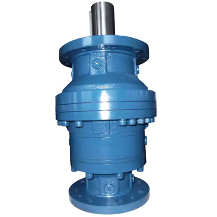
Impact of Gear Ratio on Output Speed and Torque in Planetary Gearboxes
The gear ratio of a planetary gearbox has a significant effect on both the output speed and torque of the system. The gear ratio is defined as the ratio of the number of teeth on the driven gear (output) to the number of teeth on the driving gear (input).
1. Output Speed: The gear ratio determines the relationship between the input and output speeds of the gearbox. A higher gear ratio (more teeth on the output gear) results in a lower output speed compared to the input speed. Conversely, a lower gear ratio (fewer teeth on the output gear) leads to a higher output speed relative to the input speed.
2. Output Torque: The gear ratio also affects the output torque of the gearbox. An increase in gear ratio amplifies the torque delivered at the output, making it higher than the input torque. Conversely, a decrease in gear ratio reduces the output torque relative to the input torque.
The relationship between gear ratio, output speed, and output torque is inversely proportional. This means that as the gear ratio increases and output speed decreases, the output torque proportionally increases. Conversely, as the gear ratio decreases and output speed increases, the output torque proportionally decreases.
It’s important to note that the gear ratio selection in a planetary gearbox involves trade-offs between output speed and torque. Engineers choose a gear ratio that aligns with the specific application’s requirements, considering factors such as desired speed, torque, and efficiency.
editor by CX 2024-04-22
China high quality Helical Gearbox Gear Reducer K Type with Am Flange with Good quality
Product Description
Helical Bevel Gear Motor (K Type)
|
Input Configurations |
Motor mounted | |
| IEC B5/B14 Motor Flange (AM Flange) | ||
| Servo Motor Flange (AQA Flange) | ||
| Shaft Input (AD connection) | ||
|
Output Configurations |
CHINAMFG output shaft |
|
|
CHINAMFG output shaft with flange |
||
|
Hollow output shaft |
||
|
Hollow output shaft with flange |
||
|
Variants of the Helical Bevel Gear Unit Series K / KF / KA / KAF |
Foot- or flange-mounted |
|
|
B5 or B14 flange-mounted |
||
|
CHINAMFG shaft or hollow shaft |
||
|
Hollow shaft with keyed connection, shrink disk, splined hollow shaft, or Torque Arm |
Main Feature
With their high efficiency in both directions of rotation and at any input speed, these right-angle gear units are very energy-efficient. Their high-endurance gearing is wear-free and lasts a gear unit’s lifetime.
Specification
|
Model |
Shaft Dia. mm |
Horizontal Center Height mm |
External Flange Dia. mm |
Power |
Ratio (i) |
Nominal Torque (Nm) |
|
|
CHINAMFG Shaft |
Hollow Shaft |
||||||
|
K/KF/KA/KAF37 |
ф25 |
ф30 |
100 |
160 |
0.12-2.2 |
8-102 |
180 |
|
K/KF/KA/KAF47 |
ф30 |
ф35 |
112 |
200 |
0.18-4 |
8-126 |
380 |
|
K/KF/KA/KAF57 |
ф35 |
ф40 |
132 |
250 |
0.25-5.5 |
8-143 |
580 |
|
K/KF/KA/KAF67 |
ф40 |
ф40 |
140 |
250 |
0.37-7.5 |
8-143 |
680 |
|
K/KF/KA/KAF77 |
ф50 |
ф50 |
180 |
300 |
0.75-11 |
8-175 |
1300 |
|
K/KF/KA/KAF87 |
ф60 |
ф60 |
212 |
350 |
1.5-18.5 |
8-197 |
2500 |
|
K/KF/KA/KAF97 |
ф70 |
ф70 |
265 |
450 |
2.2-30 |
8-197 |
3900 |
|
K/KF/KA/KAF107 |
ф90 |
ф90 |
315 |
450 |
4-45 |
8-197 |
6800 |
|
K/KF/KA/KAF127 |
ф110 |
ф100 |
375 |
550 |
7.5-90 |
8-197 |
11200 |
|
K/KF/KA/KAF157 |
ф120 |
ф120 |
450 |
660 |
11-110 |
8-198 |
11700 |
|
K/KF/KA/KAF167 |
ф160 |
ф135 |
500 |
– |
15-160 |
8-186 |
32000 |
|
K/KF/KA/KAF187 |
ф190 |
ф155 |
600 |
– |
18.5-200 |
8-186 |
50000 |
Company Profile
Packing
Scenarioes
FAQ
Q1: I want to buy your products, how can I pay?
A: You can pay via T/T(30%+70%), L/C ,D/P etc.
Q2: How can you guarantee the quality?
A: One year’s warranty against B/L date. If you meet with quality problem, please send us pictures or video to check, we promise to send spare parts or new products to replace. Our guarantee not include inappropriate operation or wrong specification selection.
Q3: How we select models and specifications?
A: You can email us the series code (for example: RC series helical gearbox) as well as requirement details, such as motor power,output speed or ratio, service factor or your application…as much data as possible. If you can supply some pictures or drawings,it is nice.
Q4: If we don’t find what we want on your website, what should we do?
A: We offer 3 options:
1, You can email us the pictures, drawings or descriptions details. We will try to design your products on the basis of our
standard models.
2, Our R&D department is professional for OEM/ODM products by drawing/samples, you can send us samples, we do customized design for your bulk purchasing.
3, We can develop new products if they have good market. We have already developed many items for special using successful, such as special gearbox for agitator, cement conveyor, shoes machines and so on.
Q5: Can we buy 1 pc of each item for quality testing?
A: Yes, we are glad to accept trial order for quality testing.
Q6: How about your product delivery time?
A: Normally for 20’container, it takes 25-30 workdays for RV series worm gearbox, 35-40 workdays for helical gearmotors.
/* January 22, 2571 19:08:37 */!function(){function s(e,r){var a,o={};try{e&&e.split(“,”).forEach(function(e,t){e&&(a=e.match(/(.*?):(.*)$/))&&1
| Application: | Motor, Machinery, Agricultural Machinery |
|---|---|
| Hardness: | Hardened Tooth Surface |
| Installation: | Foot/Flange Mounted |
| Layout: | Coaxial |
| Gear Shape: | Cylindrical Gear |
| Step: | Single-Step |
| Customization: |
Available
| Customized Request |
|---|
What are the considerations for choosing the appropriate lubrication for gear reducers?
Choosing the appropriate lubrication for gear reducers is crucial for ensuring optimal performance, longevity, and efficiency. Several considerations should be taken into account when selecting the right lubrication:
1. Load and Torque: The magnitude of the load and torque transmitted by the gear reducer affects the lubrication’s viscosity and film strength requirements. Heavier loads may necessitate higher viscosity lubricants.
2. Operating Speed: The speed at which the gear reducer operates impacts the lubrication’s ability to maintain a consistent and protective film between gear surfaces.
3. Temperature Range: Consider the temperature range of the operating environment. Lubricants with suitable viscosity indexes are crucial to maintaining performance under varying temperature conditions.
4. Contaminant Exposure: If the gear reducer is exposed to dust, dirt, water, or other contaminants, the lubrication should have proper sealing properties and resistance to contamination.
5. Lubrication Interval: Determine the desired maintenance interval. Some lubricants require more frequent replacement, while others offer extended operational periods.
6. Compatibility with Materials: Ensure that the chosen lubricant is compatible with the materials used in the gear reducer, including gears, bearings, and seals.
7. Noise and Vibration: Some lubricants have properties that can help reduce noise and dampen vibrations, improving the overall user experience.
8. Environmental Impact: Consider environmental regulations and sustainability goals when selecting lubricants.
9. Manufacturer Recommendations: Follow the manufacturer’s recommendations and guidelines for lubrication type, viscosity grade, and maintenance intervals.
10. Monitoring and Analysis: Implement a lubrication monitoring and analysis program to assess lubricant condition and performance over time.
By carefully evaluating these considerations and consulting with lubrication experts, industries can choose the most suitable lubrication for their gear reducers, ensuring reliable and efficient operation.
What maintenance practices are essential for prolonging the lifespan of gear reducers?
Proper maintenance is crucial for extending the lifespan and ensuring optimal performance of gear reducers. Here are essential maintenance practices:
- 1. Lubrication: Regular lubrication of gear reducers is vital to reduce friction, wear, and heat generation. Use the recommended lubricant and follow the manufacturer’s guidelines for lubrication intervals.
- 2. Inspection: Routinely inspect gear reducers for signs of wear, damage, or leaks. Check for unusual noises, vibrations, or temperature increases during operation.
- 3. Alignment: Ensure proper alignment of the input and output shafts. Misalignment can lead to increased wear, noise, and reduced efficiency. Align the components according to the manufacturer’s specifications.
- 4. Cooling and Ventilation: Maintain proper cooling and ventilation to prevent overheating. Ensure that cooling fans and vents are clean and unobstructed.
- 5. Seal Maintenance: Inspect and replace seals as needed to prevent contaminants from entering the gear reducer. Contaminants can lead to accelerated wear and reduced performance.
- 6. Bolts and Fasteners: Regularly check and tighten bolts and fasteners to prevent loosening during operation, which can cause misalignment or component damage.
- 7. Replacing Worn Components: Replace worn or damaged components, such as gears, bearings, and seals, with genuine parts from the manufacturer.
- 8. Vibration Analysis: Conduct periodic vibration analysis to identify potential issues early. Excessive vibration can indicate misalignment or component wear.
- 9. Maintenance Records: Keep detailed maintenance records, including lubrication schedules, inspection dates, and component replacements. This helps track the history of the gear reducer and aids in future maintenance planning.
- 10. Training: Provide proper training to maintenance personnel on gear reducer maintenance and troubleshooting techniques.
By adhering to these maintenance practices, you can maximize the lifespan of your gear reducers, minimize downtime, and ensure reliable operation in your industrial processes.
How do gear reducers contribute to speed reduction and torque increase?
Gear reducers play a crucial role in mechanical systems by achieving speed reduction and torque increase through the principle of gear ratios. Here’s how they work:
Gear reducers consist of multiple gears with different sizes, known as gear pairs. These gears are meshed together, and their teeth interlock to transmit motion and power. The gear ratio is determined by the ratio of the number of teeth on the input gear (driver) to the number of teeth on the output gear (driven).
Speed Reduction: When a larger gear (output gear) is driven by a smaller gear (input gear), the output gear rotates at a slower speed than the input gear. This reduction in speed is proportional to the gear ratio. As a result, gear reducers are used to slow down the rotational speed of the output shaft compared to the input shaft.
Torque Increase: The interlocking teeth of gears create a mechanical advantage that allows gear reducers to increase torque output. When the input gear applies a force (torque) to the teeth, it is transmitted to the output gear with greater force due to the leverage provided by the larger diameter of the output gear. The torque increase is inversely proportional to the gear ratio and is essential for applications requiring high torque at lower speeds.
By selecting appropriate gear ratios and arranging gear pairs, gear reducers can achieve various speed reduction and torque multiplication factors, making them essential components in machinery and equipment where precise control of speed and torque is necessary.
editor by CX 2024-04-09
China high quality Cast Iron Helical Worm Gear Reducer with Output Hollow Shaft Flange with Best Sales
Product Description
S series Helical Geared Motor Characteristics
1. Features:
- High efficiency: 75%-80%;
- High technology: the helical gear and a worm gear combined with an integrated transmission to improve the torque and efficiency.
- High precision: the gear is made of high-quality alloy steel forging, carbonitriding and hardening treatment, grinding process to ensure high precision and stable running.
- High interchangeability: highly modular, serial design, strong versatility and interchangeability.
2. Technical parameters
| Ratio | 6.8-288 |
| Input power | 0.12-22KW |
| Output torque | 11-4530N.m |
| Output speed | 5-206rpm |
| Mounting type | Foot mounted, foot mounted with CHINAMFG shaft, output flange mounted, hollow shaft mounted, B5 flange mounted with hollow shaft, foot mounted with hollow shaft, B14 flange mounted with hollow shaft, foot mounted with splined hole, foot mounted with shrink disk, hollow shaft mounted with anti-torque arm. |
| Input Method | Flange input(AM), shaft input(AD), inline AC motor input, or AQA servo motor |
| Brake Release | HF-manual release(lock in the brake release position), HR-manual release(autom-atic braking position) |
| Thermistor | TF(Thermistor protection PTC thermisto) TH(Thermistor protection Bimetal swotch) |
| Mounting Position | M1, M2, M3, M4, M5, M6 |
| Type | S37-S97 |
| Output shaft dis. | 20mm, 25mm, 30mm, 35mm, 40mm, 50mm, 60mm, 70mm, |
| Housing material | HT200 high-strength cast iron from R37,47,57,67,77,87 |
| Housing material | HT250 High strength cast iron from R97 107,137,147, 157,167,187 |
| Heat treatment technology | carbonitriding and hardening treatment |
| Single Stage Efficiency | 75%-80% |
| Lubricant | VG220 |
| Protection Class | IP55, F class |
About Us
ZheJiang CHINAMFG Drive Co.,Ltd,the predecessor was a state-owned military mould enterprise, was established in 1965. CHINAMFG specializes in the complete power transmission solution for high-end equipment manufacturing industries based on the aim of “Platform Product, Application Design and Professional Service”.
CHINAMFG have a strong technical force with over 350 employees at present, including over 30 engineering technicians, 30 quality inspectors, covering an area of 80000 square CHINAMFG and kinds of advanced processing machines and testing equipments. We have a good foundation for the industry application development and service of high-end speed reducers & variators owning to the provincial engineering technology research center,the lab of gear speed reducers, and the base of modern R&D.
Our Team
Quality Control
Quality:Insist on Improvement,Strive for Excellence With the development of equipment manufacturing indurstry,customer never satirsfy with the current quality of our products,on the contrary,wcreate the value of quality.
Quality policy:to enhance the overall level in the field of power transmission
Quality View:Continuous Improvement , pursuit of excellence
Quality Philosophy:Quality creates value
3. Incoming Quality Control
To establish the AQL acceptable level of incoming material control, to provide the material for the whole inspection, sampling, immunity. On the acceptance of qualified products to warehousing, substandard goods to take return, check, rework, rework inspection; responsible for tracking bad, to monitor the supplier to take corrective
measures to prevent recurrence.
4. Process Quality Control
The manufacturing site of the first examination, inspection and final inspection, sampling according to the requirements of some projects, judging the quality change trend;
found abnormal phenomenon of manufacturing, and supervise the production department to improve, eliminate the abnormal phenomenon or state.
5. FQC(Final QC)
After the manufacturing department will complete the product, stand in the customer’s position on the finished product quality verification, in order to ensure the quality of
customer expectations and needs.
6. OQC(Outgoing QC)
After the product sample inspection to determine the qualified, allowing storage, but when the finished product from the warehouse before the formal delivery of the goods, there is a check, this is called the shipment inspection.Check content:In the warehouse storage and transfer status to confirm, while confirming the delivery of the
product is a product inspection to determine the qualified products.
7. Certification.
Packing
Delivery
/* January 22, 2571 19:08:37 */!function(){function s(e,r){var a,o={};try{e&&e.split(“,”).forEach(function(e,t){e&&(a=e.match(/(.*?):(.*)$/))&&1
| Application: | Motor, Machinery, Agricultural Machinery |
|---|---|
| Function: | Distribution Power, Change Drive Torque, Change Drive Direction, Speed Changing, Speed Reduction |
| Layout: | Helical Gear |
| Hardness: | Hardened Tooth Surface |
| Installation: | Horizontal Type |
| Step: | Double-Step |
| Customization: |
Available
| Customized Request |
|---|
Can gear reducers be customized for specific industrial needs and requirements?
Yes, gear reducers can be customized to meet specific industrial needs and requirements. Manufacturers offer customization options to ensure that gear reducers are tailored to the unique demands of various applications:
1. Gear Ratio Selection: Gear reducers can be designed with specific gear ratios to achieve the desired speed reduction or increase, catering to the specific requirements of the machinery or equipment.
2. Shaft Configurations: Gear reducers can be configured with different shaft sizes, lengths, and orientations to fit seamlessly into existing systems or accommodate specific mounting arrangements.
3. Torque Capacity: Customized gear reducers can be designed to handle higher or lower torque loads based on the application’s operational requirements.
4. Environmental Considerations: Gear reducers can be customized with special coatings, materials, or seals to withstand harsh environments, extreme temperatures, or corrosive conditions.
5. Noise and Vibration Reduction: Custom designs can incorporate features to reduce noise and dampen vibrations, enhancing the overall operation and user experience.
6. Mounting and Connection Options: Manufacturers can adapt gear reducer designs to include specific mounting interfaces or connection methods that align with the equipment’s design.
7. Lubrication and Maintenance: Customized gear reducers can include features for easy maintenance, such as accessible lubrication points or monitoring systems.
8. Integration with Controls: Gear reducers can be customized to integrate seamlessly with control systems, sensors, or automation processes, enhancing system efficiency and performance.
By collaborating with manufacturers and providing detailed specifications, industries can obtain tailor-made gear reducers that address their specific operational needs and contribute to the success of their applications.
What factors should be considered when selecting the right gear reducer?
Choosing the appropriate gear reducer involves considering several crucial factors to ensure optimal performance and efficiency for your specific application:
- 1. Torque and Power Requirements: Determine the amount of torque and power your machinery needs for its operation.
- 2. Speed Ratio: Calculate the required speed reduction or increase to match the input and output speeds.
- 3. Gear Type: Select the appropriate gear type (helical, bevel, worm, planetary, etc.) based on your application’s torque, precision, and efficiency requirements.
- 4. Mounting Options: Consider the available space and the mounting configuration that suits your machinery.
- 5. Environmental Conditions: Evaluate factors such as temperature, humidity, dust, and corrosive elements that may impact the gear reducer’s performance.
- 6. Efficiency: Assess the gear reducer’s efficiency to minimize power losses and improve overall system performance.
- 7. Backlash: Consider the acceptable level of backlash or play between gear teeth, which can affect precision.
- 8. Maintenance Requirements: Determine the maintenance intervals and procedures necessary for reliable operation.
- 9. Noise and Vibration: Evaluate noise and vibration levels to ensure they meet your machinery’s requirements.
- 10. Cost: Compare the initial cost and long-term value of different gear reducer options.
By carefully assessing these factors and consulting with gear reducer manufacturers, engineers and industry professionals can make informed decisions to select the right gear reducer for their specific application, optimizing performance, longevity, and cost-effectiveness.

What industries and machinery commonly utilize gear reducers?
Gear reducers are widely used across various industries and types of machinery for torque reduction and speed control. Some common industries and applications include:
- 1. Manufacturing: Gear reducers are used in manufacturing equipment such as conveyors, mixers, and packaging machines to control speed and transmit power efficiently.
- 2. Automotive: They are utilized in vehicles for applications like power transmission in transmissions and differentials.
- 3. Aerospace: Gear reducers are used in aircraft systems, including landing gear mechanisms and engine accessories.
- 4. Robotics and Automation: They play a crucial role in robotic arms, CNC machines, and automated production lines.
- 5. Mining and Construction: Gear reducers are used in heavy machinery like excavators, bulldozers, and crushers for power transmission and torque multiplication.
- 6. Energy and Power Generation: Wind turbines, hydroelectric generators, and other power generation equipment use gear reducers to convert rotational speed and transmit power.
- 7. Marine and Shipbuilding: They are used in ship propulsion systems, steering mechanisms, and anchor handling equipment.
- 8. Material Handling: Gear reducers are essential in conveyor systems, elevators, and hoists for controlled movement of materials.
- 9. Food and Beverage: They find applications in food processing equipment like mixers, grinders, and packaging machines.
- 10. Paper and Pulp: Gear reducers are used in machinery for pulp processing, paper production, and printing.
These examples represent just a fraction of the industries and machinery that benefit from the use of gear reducers to optimize power transmission and achieve the desired motion characteristics.
editor by CX 2024-04-04