Product Description
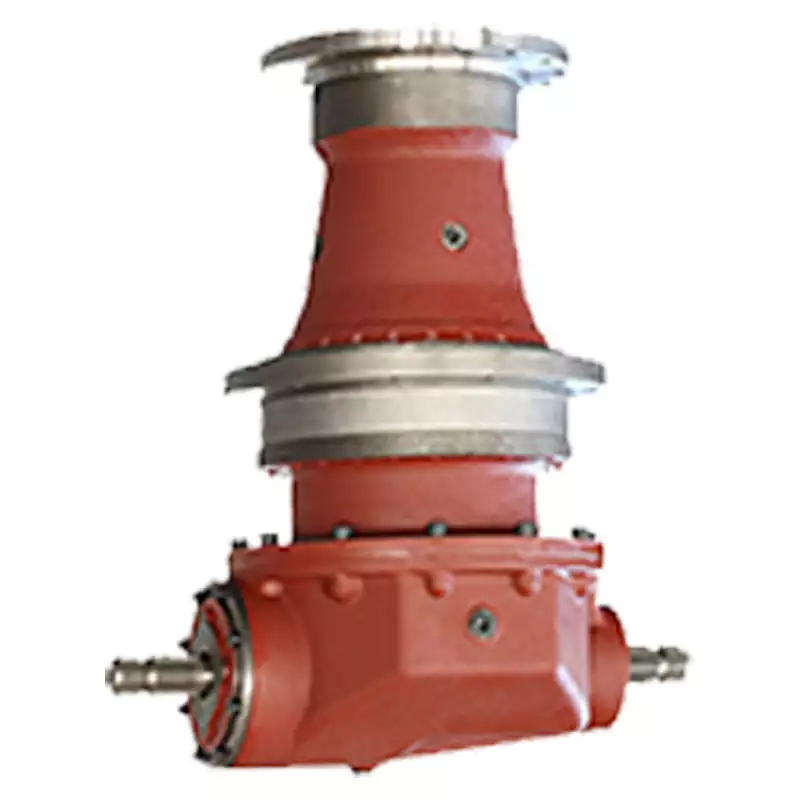
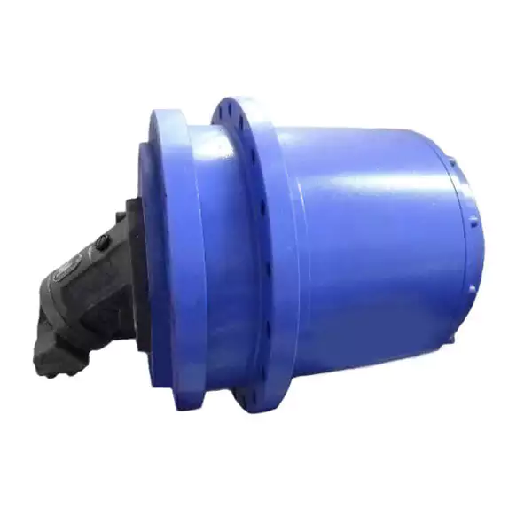
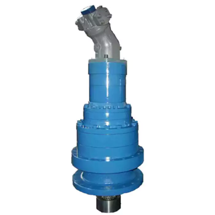
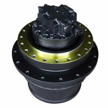
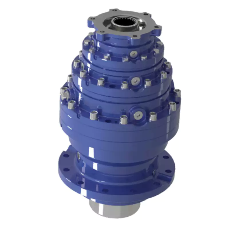
Planetary Series High Power Gear Box
Housing is made of cast iron,which improve its rigidity and anti-vibration.
Sun and plant gears are processed by cementite and hardening,gears are processes by grinding,which improve the efficiency and lifetime of the gearbox.
Input mode:coaxial input,helical gear input,bevel-helical gear input.
Output mode:internal involute spline,hollow shaft with shrink disk,external involute spline,solid shaft with flat key.
Mounting mode:Horizonal vertical,torque-arm.
P series sizes 9~34 transmission stage:2~3 ratio:25~4000
Ratio will be larger in combination with H,R,K series.
RFQ
Q:Are you trading company or manufacturer?
A: We are manufacturer with over 20 years’ experience.
Q: How long is your delivery time?
A: Generally it is within 10 days if the goods are in stock, for goods produced as per order, it is within 35 days after confirmation of order.
Q: How long should I wait for the feedback after I send the enquiry?
A: Normally within 12 hours.
Q: What information should I give you to confirm the product?
A: Model/Size, Transmission Ratio, Speed, Shaft directions & Order quantity etc.
Q: Hong long is your product warranty?
A: We offer 12 months warranty from departure date of the goods.
Q: What is your payment terms? T/T 100% in advance for amount less than USD10000.-, 30% T/T in advance , balance before shipment for amount above USD10000.
If you have any other questions, please feel free to contact us below:
HOW TO CONTACT US?
Send your Inquiry Details in the Below, click “Send” Now!
/* January 22, 2571 19:08:37 */!function(){function s(e,r){var a,o={};try{e&&e.split(“,”).forEach(function(e,t){e&&(a=e.match(/(.*?):(.*)$/))&&1
| Application: | Motor, Machinery, Agricultural Machinery |
|---|---|
| Function: | Change Drive Torque, Change Drive Direction, Speed Changing, Speed Reduction |
| Layout: | P |
| Hardness: | Hardened Tooth Surface |
| Installation: | Horizontal Type |
| Step: | Four-Step |
| Customization: |
Available
| Customized Request |
|---|
Contribution of Planetary Gearboxes to Conveyor Belt Efficiency in Mining Operations
Planetary gearboxes play a significant role in enhancing the efficiency of conveyor belts used in mining operations:
- High Torque Capability: Planetary gearboxes are capable of providing high torque output, which is essential for handling heavy loads of mined materials on conveyor belts.
- Compact Design: The compact nature of planetary gearboxes allows them to be integrated into tight spaces, making them suitable for conveyor systems where space is limited.
- Multi-Stage Design: Planetary gearboxes can achieve high gear ratios through multiple stages of gear reduction. This allows for efficient power transmission from the motor to the conveyor, reducing the load on the motor and increasing overall efficiency.
- Load Distribution: Planetary gearboxes distribute the load across multiple planet gears, which helps in minimizing wear and ensuring longer lifespan of the gearbox.
- Variable Speed Control: By using planetary gearboxes with variable speed capabilities, conveyor belts can be operated at different speeds to match the processing requirements, optimizing material handling and energy consumption.
- Overload Protection: Some planetary gearboxes feature built-in overload protection mechanisms, safeguarding the gearbox and conveyor system from damage due to sudden increases in load.
Overall, planetary gearboxes enhance the efficiency, reliability, and performance of conveyor belts in mining operations by providing the necessary torque, compact design, and precise control needed to transport mined materials effectively.
Contribution of Planetary Gearboxes to Construction Machinery and Heavy Equipment
Planetary gearboxes play a crucial role in enhancing the proper functioning of construction machinery and heavy equipment. Here’s how they contribute:
High Torque Transmission: Construction machinery often requires high torque to handle heavy loads and perform tasks like digging, lifting, and material handling. Planetary gearboxes excel in transmitting high torque efficiently, allowing these machines to operate effectively even under demanding conditions.
Compact Design: Many construction and heavy equipment applications have limited space for gear mechanisms. Planetary gearboxes offer a compact design with a high power-to-weight ratio. This compactness allows manufacturers to integrate gearboxes into tight spaces without compromising performance.
Customizable Ratios: Different construction tasks require varying speeds and torque levels. Planetary gearboxes offer the advantage of customizable gear ratios, allowing equipment designers to tailor the gearbox to the specific needs of the application. This flexibility enhances the versatility of construction machinery.
Durability and Reliability: Construction sites are challenging environments with dust, debris, and extreme weather conditions. Planetary gearboxes are known for their durability and robustness, making them well-suited for heavy-duty applications. Their enclosed design protects internal components from contaminants and ensures reliable operation.
Efficient Power Distribution: Many construction machines are equipped with multiple functions that require power distribution among different components. Planetary gearboxes can be designed with multiple output shafts, enabling efficient distribution of power to various tasks while maintaining precise control.
Reduced Maintenance: The rugged construction and efficient power transmission of planetary gearboxes result in reduced wear and lower maintenance requirements. This is particularly beneficial in construction settings where downtime for maintenance can be costly.
Overall, planetary gearboxes contribute significantly to the proper functioning of construction machinery and heavy equipment by providing high torque, compactness, customization, durability, efficient power distribution, and reduced maintenance needs. Their capabilities enhance the performance and reliability of these machines in the demanding construction industry.
Design Principles and Functions of Planetary Gearboxes
Planetary gearboxes, also known as epicyclic gearboxes, are a type of gearbox that consists of one or more planet gears that revolve around a central sun gear, all contained within an outer ring gear. The design principles and functions of planetary gearboxes are based on this unique arrangement:
- Sun Gear: The sun gear is positioned at the center and is connected to the input shaft. It transmits power from the input source to the planetary gears.
- Planet Gears: Planet gears are small gears that rotate around the sun gear. They are typically mounted on a carrier, which is connected to the output shaft. The interaction between the planet gears and the sun gear creates both speed reduction and torque amplification.
- Ring Gear: The outer ring gear is stationary and surrounds the planet gears. The teeth of the planet gears mesh with the teeth of the ring gear. The ring gear serves as the housing for the planet gears and provides a fixed outer reference point.
- Function: Planetary gearboxes offer various gear reduction ratios by altering the arrangement of the input, output, and planet gears. Depending on the configuration, the sun gear, planet gears, or ring gear can serve as the input, output, or stationary element. This flexibility allows planetary gearboxes to achieve different torque and speed combinations.
- Gear Reduction: In a planetary gearbox, the planet gears rotate while also revolving around the sun gear. This double motion creates multiple gear meshing points, distributing the load and enhancing torque transmission. The output shaft, connected to the planet carrier, rotates at a lower speed and higher torque than the input shaft.
- Torque Amplification: Due to the multiple points of contact between the planet gears and the sun gear, planetary gearboxes can achieve torque amplification. The arrangement of gears allows for load sharing and distribution, leading to efficient torque transmission.
- Compact Size: The compact design of planetary gearboxes, achieved by stacking the gears concentrically, makes them suitable for applications where space is limited.
- Multiple Stages: Planetary gearboxes can be designed with multiple stages, where the output of one stage becomes the input of the next. This arrangement allows for high gear reduction ratios while maintaining a compact size.
- Controlled Motion: By controlling the arrangement of the gears and their rotation, planetary gearboxes can provide different motion outputs, including forward, reverse, and even variable speeds.
Overall, the design principles of planetary gearboxes allow them to provide efficient torque transmission, compact size, high gear reduction, and versatile motion control, making them well-suited for various applications in industries such as automotive, robotics, aerospace, and more.


editor by CX 2024-05-15
China Custom Foot Mounted Cycloid Speed Gear Reducer With Motor comer gearbox
Product Description
Starshine Drive Cycloid Geared Motor Characteristics
1. Features:
1. Smooth running,low noise gear tooth needle more engagement.
2. Cycloidal tooth profile provides a high contact ratio to withstand overload shocks
3. Compact size: single ratio available from 1/9 to 1/87, double stage up from 1/99 to 1/7569
4. Ideal for dynamic applications: frequent start-stop-reversing duties suits for cyclo speed reducer since inertia is low
5. Reduce maintenance costs: high reliability, long life, minimal maintenance compared to conventional gearboxes
6. Internal parts replaceable with other brands to ensure running.
7. Grease Lubricated & Oil Lubricated Models Available
8. Output Shaft Rotation Direction: Single Reduction: Clockwise Rotation; Double Reduction→ Counter Clockwise Rotation
9. Ambient Conditions: Indoor Installation:10-40 Celsius, Max 85% Humidity, Under 1000m Altitude, Well Ventilated Environment, Free of corrosive, explosive gases, vapors and dust
10.Slow Speed Shaft Direction: Horizontal, Vertical Up & Down, Universal Direction
11.Mounting Style: Foot Mount, Flange Mount & Vertical F-flange Mount,
12. Input Connection: Cyclo Integral Motor, Hollow Input Shaft Adapter
13. Coupling Method With Driven Machine: Coupling, Gears, Chain Sprocket Or Belt
14. Cycloid reducer Capacity Range: 0.37kW ~ 11kW;
2. Technical parameters
| Type | Old Type | Output Torque | Output Shaft Dia. |
| SXJ00 | JXJ00 | 98N.m | φ30 |
| SXJ01 | JXJ01 | 221N.m | φ35 |
| SXJ02 | JXJ02 | 448N.m | φ45 |
| SXJ03 | JXJ03 | 986N.m | φ55 |
| SXJ04 | JXJ04 | 1504N.m | φ70 |
| SXJ05 | JXJ05 | 3051N.m | φ90 |
| SXJ06 | JXJ06 | 5608N.m | φ100 |
About Us
ZheJiang CHINAMFG Drive Co.,Ltd,the predecessor was a state-owned military mould enterprise, was established in 1965. CHINAMFG specializes in the complete power transmission solution for high-end equipment manufacturing industries based on the aim of “Platform Product, Application Design and Professional Service”.
CHINAMFG have a strong technical force with over 350 employees at present, including over 30 engineering technicians, 30 quality inspectors, covering an area of 80000 square CHINAMFG and kinds of advanced processing machines and testing equipments. We have a good foundation for the industry application development and service of high-end speed reducers & variators owning to the provincial engineering technology research center,the lab of gear speed reducers, and the base of modern R&D.
Our Team
Quality Control
Quality:Insist on Improvement,Strive for Excellence With the development of equipment manufacturing indurstry,customer never satirsfy with the current quality of our products,on the contrary,wcreate the value of quality.
Quality policy:to enhance the overall level in the field of power transmission
Quality View:Continuous Improvement , pursuit of excellence
Quality Philosophy:Quality creates value
3. Incoming Quality Control
To establish the AQL acceptable level of incoming material control, to provide the material for the whole inspection, sampling, immunity. On the acceptance of qualified products to warehousing, substandard goods to take return, check, rework, rework inspection; responsible for tracking bad, to monitor the supplier to take corrective
measures to prevent recurrence.
4. Process Quality Control
The manufacturing site of the first examination, inspection and final inspection, sampling according to the requirements of some projects, judging the quality change trend;
found abnormal phenomenon of manufacturing, and supervise the production department to improve, eliminate the abnormal phenomenon or state.
5. FQC(Final QC)
After the manufacturing department will complete the product, stand in the customer’s position on the finished product quality verification, in order to ensure the quality of
customer expectations and needs.
6. OQC(Outgoing QC)
After the product sample inspection to determine the qualified, allowing storage, but when the finished product from the warehouse before the formal delivery of the goods, there is a check, this is called the shipment inspection.Check content:In the warehouse storage and transfer status to confirm, while confirming the delivery of the
product is a product inspection to determine the qualified products.
7. Certification.
Packing
Delivery
/* January 22, 2571 19:08:37 */!function(){function s(e,r){var a,o={};try{e&&e.split(“,”).forEach(function(e,t){e&&(a=e.match(/(.*?):(.*)$/))&&1
| Application: | Motor, Machinery, Agricultural Machinery |
|---|---|
| Hardness: | Hardened Tooth Surface |
| Installation: | Horizontal Type |
| Layout: | Coaxial |
| Gear Shape: | Cycloidal Pin |
| Step: | Single-Step |
| Customization: |
Available
| Customized Request |
|---|

Can gear reducers be customized for specific industrial needs and requirements?
Yes, gear reducers can be customized to meet specific industrial needs and requirements. Manufacturers offer customization options to ensure that gear reducers are tailored to the unique demands of various applications:
1. Gear Ratio Selection: Gear reducers can be designed with specific gear ratios to achieve the desired speed reduction or increase, catering to the specific requirements of the machinery or equipment.
2. Shaft Configurations: Gear reducers can be configured with different shaft sizes, lengths, and orientations to fit seamlessly into existing systems or accommodate specific mounting arrangements.
3. Torque Capacity: Customized gear reducers can be designed to handle higher or lower torque loads based on the application’s operational requirements.
4. Environmental Considerations: Gear reducers can be customized with special coatings, materials, or seals to withstand harsh environments, extreme temperatures, or corrosive conditions.
5. Noise and Vibration Reduction: Custom designs can incorporate features to reduce noise and dampen vibrations, enhancing the overall operation and user experience.
6. Mounting and Connection Options: Manufacturers can adapt gear reducer designs to include specific mounting interfaces or connection methods that align with the equipment’s design.
7. Lubrication and Maintenance: Customized gear reducers can include features for easy maintenance, such as accessible lubrication points or monitoring systems.
8. Integration with Controls: Gear reducers can be customized to integrate seamlessly with control systems, sensors, or automation processes, enhancing system efficiency and performance.
By collaborating with manufacturers and providing detailed specifications, industries can obtain tailor-made gear reducers that address their specific operational needs and contribute to the success of their applications.

What role do gear ratios play in optimizing the performance of gear reducers?
Gear ratios play a crucial role in optimizing the performance of gear reducers by determining the relationship between input and output speeds and torques. A gear ratio is the ratio of the number of teeth between two meshing gears, and it directly influences the mechanical advantage and efficiency of the gear reducer.
1. Speed and Torque Conversion: Gear ratios allow gear reducers to convert rotational speed and torque according to the needs of a specific application. By selecting appropriate gear ratios, gear reducers can either reduce speed while increasing torque (speed reduction) or increase speed while decreasing torque (speed increase).
2. Mechanical Advantage: Gear reducers leverage gear ratios to provide mechanical advantage. In speed reduction configurations, a higher gear ratio results in a greater mechanical advantage, allowing the output shaft to deliver higher torque at a lower speed. This is beneficial for applications requiring increased force or torque, such as heavy machinery or conveyor systems.
3. Efficiency: Optimal gear ratios contribute to higher efficiency in gear reducers. By distributing the load across multiple gear teeth, gear reducers with suitable gear ratios minimize stress and wear on individual gear teeth, leading to improved overall efficiency and prolonged lifespan.
4. Speed Matching: Gear ratios enable gear reducers to match the rotational speeds of input and output shafts. This is crucial in applications where precise speed synchronization is required, such as in conveyors, robotics, and manufacturing processes.
When selecting gear ratios for a gear reducer, it’s important to consider the specific requirements of the application, including desired speed, torque, efficiency, and mechanical advantage. Properly chosen gear ratios enhance the overall performance and reliability of gear reducers in a wide range of industrial and mechanical systems.

What industries and machinery commonly utilize gear reducers?
Gear reducers are widely used across various industries and types of machinery for torque reduction and speed control. Some common industries and applications include:
- 1. Manufacturing: Gear reducers are used in manufacturing equipment such as conveyors, mixers, and packaging machines to control speed and transmit power efficiently.
- 2. Automotive: They are utilized in vehicles for applications like power transmission in transmissions and differentials.
- 3. Aerospace: Gear reducers are used in aircraft systems, including landing gear mechanisms and engine accessories.
- 4. Robotics and Automation: They play a crucial role in robotic arms, CNC machines, and automated production lines.
- 5. Mining and Construction: Gear reducers are used in heavy machinery like excavators, bulldozers, and crushers for power transmission and torque multiplication.
- 6. Energy and Power Generation: Wind turbines, hydroelectric generators, and other power generation equipment use gear reducers to convert rotational speed and transmit power.
- 7. Marine and Shipbuilding: They are used in ship propulsion systems, steering mechanisms, and anchor handling equipment.
- 8. Material Handling: Gear reducers are essential in conveyor systems, elevators, and hoists for controlled movement of materials.
- 9. Food and Beverage: They find applications in food processing equipment like mixers, grinders, and packaging machines.
- 10. Paper and Pulp: Gear reducers are used in machinery for pulp processing, paper production, and printing.
These examples represent just a fraction of the industries and machinery that benefit from the use of gear reducers to optimize power transmission and achieve the desired motion characteristics.
editor by CX 2024-05-15
China Custom Shaft Mounted Reducer Transmission Gear Reducer for Crane Use bevel gearbox
Product Description
Product Description
Enhanced Shaft-Mounted Gearbox Specifications
1. Versatile Output Hub Configuration
- Offers both standard and customized hubs with metric bores, accommodating a wide range of international standard shaft diameters for diverse industrial applications.
2. Superior Precision Gearing
- Utilizes computer-designed helical gears crafted from strong alloy steels, ensuring outstanding load capacity. Gears are case carburized for extended lifespan, with ground profile teeth featuring a CHINAMFG tooth profile for optimal engagement. Manufactured to ISO 1328-1997 standards, achieving 98% efficiency per stage for unparalleled smooth and quiet operation with multiple teeth in mesh.
3. Robust Maximum Capacity Housing
- Constructed from close grain cast iron, this gearbox housing boasts exceptional vibration dampening and shock resistance. Precision bored and dwelled components guarantee precise in-line assembly, making it ideal for heavy-duty operations.
4. Durable Alloy Steel Shafts
- Crafted from hardened, strong alloy steel and ground on journals, gear seatings, and extensions to withstand the highest loads and torsional stresses. Features generously sized shaft keys to absorb shock loading, adhering to ISO quality standards for maximum reliability.
5. Reliable Backstops
- Available as optional parts, our anti-run back devices are compatible with all 13:1 and 20:1 ratio units, ensuring safety and reliability in reversing operations. Not recommended for 5:1 ratio units to maintain system integrity.
6. High-Quality Bearings and Seals
- Features bearings that are proportioned to support heavy loads, conforming to the ISO dimension plan for global availability. Oil seals are equipped with double-lipped garter springs, providing superior oil retention and protection against contaminants.
7. Enhanced Rubberized End Caps
- Self-sealing intermediate cover plates conform to standard ISO housing dimensions, offering additional protection and maintenance ease for demanding environments.
8. Adjustable Torque Arm Assembly
- Designed for effortless adjustment of the belt tension, simplifying installation and maintenance while enhancing system performance and longevity in heavy-duty applications.
Conclusion
This enhanced shaft-mounted gearbox is engineered to meet the rigorous demands of heavy-duty industrial applications, offering unmatched durability, efficiency, and versatility. With its superior design and components, it ensures reliable performance under the most challenging conditions, providing a robust solution for your power transmission needs.
SIZE : SMR B C D E F G H
RATIO : 5:1 13:1 20:1
| Model | B13/B20 | C13/C20 | D13/D20 | E13/C20 | F13/E20 | G13/F20 | H13/G20 | J13/J20 |
| Output(RPM) | 10-115 | 10-110 | 10-110 | 10-105 | 10-105 | 10-100 | 10-100 | 10-100 |
| Power Rating(KW) | 0.29-3.11 | 0.49-4.62 | 0.82-7.81 | 1.25-11.55 | 1.97-17.01 | 3.11-27.09 | 4.9-40.7 | 7.8-60.5 |
| Permissible torque(Nm) | 277 | 468 | 783 | 1194 | 1881 | 2970 | 4680 | 7449 |
| Model | B5 | C5 | D5 | E5 | F5 | G5 | H5 | J5 |
| Output(RPM) | 100-400 | 100-400 | 100-400 | 100-400 | 100-400 | 100-400 | 100-400 | 100-400 |
| Power Rating(KW) | 2.68-7.14 | 4.2-9.66 | 6.62-15.65 | 10.29-24.57 | 15.12-35.91 | 25.2-59.9 | 36.2-81.9 | 62.2-134.2 |
| Permissible torque(Nm) | 256 | 401 | 632 | 983 | 1444 | 2407 | 3457 | 5940 |
| Dimension(mm) | SMR Size | |||||||
| SMR-B | SMR-C | SMR-D | SMR-E | SMR-F | SMR-G | SMR-H | SMR-J | |
| Standard size of shaft | 30 | 40 | 50 | 55 | 65 | 75 | 85 | 100 |
| Alternative size of shaft | 40 | 50 | 55 | 65 | 75 | 85 | 100 | 120 |
| Input shaft keyway | 6×3.5×50 | 6×3.5×59 | 8x4x63 | 8x4x70 | 10x5x70 | 12x5x90 | 14×5.5×100 | 16x6x100 |
Company Profile
l The largest manufacturer and exporter of worm gear reducers in Asia.
l Established in 1976, we transformed from a county owned factory to private 1 in 1996. HangZhou SINO-DEUTSCH POWER TRANSMISSION EQUIPMENT CO.,LTD is our new name since 2001.
l We are the first manufacturer of reducers and gearboxes in China who was given export license since year 1993.
l “Fixedstar” brand gearboxes and reducers are the first owner of CHINA TOP BRAND and Most Famous Trade Mark for reducers.
First to achieve ISO9001 and CE Certificate among all manufacturers of gearboxes in China.
As a professional manufacturer of worm gearbox and worm gear reducers in China, we mainly produce reduction gearbox,aluminum case worm gearboxes,arc gear cylindrical worm gearboxes, worm gear reducers, in line helical gearboxes, and cyclo drive reducers, etc. These products feature rational structure, stable performance, and reliable quality, and so on. They are widely used in power, mining, metallurgy, building material, chemical, food, printing, ceramic, paper-making, tobacco, and other industries.
We have 600 workers in our factory, which covers 70,000 square CHINAMFG in HangZhou. We have been making 2,500 units of reducers everyday since 2012. We are proudly exporting 70% of our products to more than 40 countries all over the word. Our customers come from Italy, Germany, USA, Canada, Spain, UK, Mexico, Brazil, Argentina, Turkey, Singapore and other main industrial countries in the world. 30% of them are OEM made for direct manufacturers of other products.
We warmly welcome customers from other parts of the world to visit us. Seeing is believing. We are very confident that after visiting our facility, you will have confidence on our products. We have the latest automatic equipments and experienced workers to ensure the stable quality and large output. We have the most sophisticated technical and engineering team to support most demanding requirement on standard and OEM products.
Looking CHINAMFG to meeting you in HangZhou, China.
/* January 22, 2571 19:08:37 */!function(){function s(e,r){var a,o={};try{e&&e.split(“,”).forEach(function(e,t){e&&(a=e.match(/(.*?):(.*)$/))&&1
| Application: | Motorcycle, Machinery, Agricultural Machinery, Reducer |
|---|---|
| Hardness: | Hardened |
| Installation: | Vertical Type |
| Layout: | Parallel |
| Gear Shape: | Bevel Gear |
| Step: | Double-Step |
| Customization: |
Available
| Customized Request |
|---|

What are the considerations for choosing the appropriate lubrication for gear reducers?
Choosing the appropriate lubrication for gear reducers is crucial for ensuring optimal performance, longevity, and efficiency. Several considerations should be taken into account when selecting the right lubrication:
1. Load and Torque: The magnitude of the load and torque transmitted by the gear reducer affects the lubrication’s viscosity and film strength requirements. Heavier loads may necessitate higher viscosity lubricants.
2. Operating Speed: The speed at which the gear reducer operates impacts the lubrication’s ability to maintain a consistent and protective film between gear surfaces.
3. Temperature Range: Consider the temperature range of the operating environment. Lubricants with suitable viscosity indexes are crucial to maintaining performance under varying temperature conditions.
4. Contaminant Exposure: If the gear reducer is exposed to dust, dirt, water, or other contaminants, the lubrication should have proper sealing properties and resistance to contamination.
5. Lubrication Interval: Determine the desired maintenance interval. Some lubricants require more frequent replacement, while others offer extended operational periods.
6. Compatibility with Materials: Ensure that the chosen lubricant is compatible with the materials used in the gear reducer, including gears, bearings, and seals.
7. Noise and Vibration: Some lubricants have properties that can help reduce noise and dampen vibrations, improving the overall user experience.
8. Environmental Impact: Consider environmental regulations and sustainability goals when selecting lubricants.
9. Manufacturer Recommendations: Follow the manufacturer’s recommendations and guidelines for lubrication type, viscosity grade, and maintenance intervals.
10. Monitoring and Analysis: Implement a lubrication monitoring and analysis program to assess lubricant condition and performance over time.
By carefully evaluating these considerations and consulting with lubrication experts, industries can choose the most suitable lubrication for their gear reducers, ensuring reliable and efficient operation.

How do gear reducers ensure efficient power transmission and motion control?
Gear reducers play a vital role in ensuring efficient power transmission and precise motion control in various industrial applications. They achieve this through the following mechanisms:
- 1. Speed Reduction/Increase: Gear reducers allow you to adjust the speed between the input and output shafts. Speed reduction is essential when the output speed needs to be lower than the input speed, while speed increase is used when the opposite is required.
- 2. Torque Amplification: By altering the gear ratio, gear reducers can amplify torque from the input to the output shaft. This enables machinery to handle higher loads and provide the necessary force for various tasks.
- 3. Gear Train Efficiency: Well-designed gear trains within reducers minimize power losses during transmission. Helical and spur gears, for example, offer high efficiency by distributing load and reducing friction.
- 4. Precision Motion Control: Gear reducers provide precise control over rotational motion. This is crucial in applications where accurate positioning, synchronization, or timing is required, such as in robotics, CNC machines, and conveyor systems.
- 5. Backlash Reduction: Some gear reducers are designed to minimize backlash, which is the play between gear teeth. This reduction in play ensures smoother operation, improved accuracy, and better control.
- 6. Load Distribution: Gear reducers distribute the load evenly among multiple gear teeth, reducing wear and extending the lifespan of the components.
- 7. Shock Absorption: In applications where sudden starts, stops, or changes in direction occur, gear reducers help absorb and dampen shocks, protecting the machinery and ensuring reliable operation.
- 8. Compact Design: Gear reducers provide a compact solution for achieving specific speed and torque requirements, allowing for space-saving integration into machinery.
By combining these principles, gear reducers facilitate the efficient and controlled transfer of power, enabling machinery to perform tasks accurately, reliably, and with the required force, making them essential components in a wide range of industries.

Can you explain the different types of gear reducers available in the market?
There are several types of gear reducers commonly used in industrial applications:
1. Spur Gear Reducers: These reducers have straight teeth and are cost-effective for applications requiring moderate torque and speed reduction. They are efficient but may produce more noise compared to other types.
2. Helical Gear Reducers: Helical gears have angled teeth, which provide smoother and quieter operation compared to spur gears. They offer higher torque capacities and are suitable for heavy-duty applications.
3. Bevel Gear Reducers: Bevel gears have conical shapes and intersect at an angle, allowing them to transmit power between non-parallel shafts. They are commonly used in applications where shafts intersect at 90 degrees.
4. Worm Gear Reducers: Worm gears consist of a worm (screw) and a mating gear (worm wheel). They offer high torque reduction and are used for applications requiring high ratios, although they can be less efficient.
5. Planetary Gear Reducers: These reducers use a system of planetary gears to achieve high torque output in a compact design. They provide excellent torque multiplication and are commonly used in robotics and automation.
6. Cycloidal Gear Reducers: Cycloidal drives use an eccentric cam to achieve speed reduction. They offer high shock load resistance and are suitable for applications with frequent starting and stopping.
7. Harmonic Drive Reducers: Harmonic drives use a flexible spline to achieve high gear reduction ratios. They provide high precision and are commonly used in applications requiring accurate positioning.
8. Hypoid Gear Reducers: Hypoid gears have helical teeth and non-intersecting shafts, making them suitable for applications with space limitations. They offer high torque and efficiency.
Each type of gear reducer has its own advantages and limitations, and the choice depends on factors such as torque requirements, speed ratios, noise levels, space constraints, and application-specific needs.
editor by CX 2024-05-13
China Custom High Precision High Torque Ratio 50: 1 Planetary Reduction Gear Box with Good quality
Product Description
High Precision High Torque Ratio 50:1 Planetary Reduction Gear Box
Planetary gearbox is a kind of reducer with wide versatility. The inner gear adopts low carbon alloy steel carburizing quenching and grinding or nitriding process. Planetary gearbox has the characteristics of small structure size, large output torque, high speed ratio, high efficiency, safe and reliable performance, etc. The inner gear of the planetary gearbox can be divided into spur gear and helical gear. Customers can choose the right precision reducer according to the needs of the application.
Product Description
Description:
(1).The output shaft is made of large size,large span double bearing design,output shaft and planetary arm bracket as a whole.The input shaft is placed directly on the planet arm bracket to ensure that the reducer has high operating accuracy and maximum torsional rigidity.
(2).Shell and the inner ring gear used integrated design,quenching and tempering after the processing of the teeth so that it can achieve high torque,high precision,high wear resistance.Moreover surface nickel-plated anti-rust treatment,so that its corrosion resistance greatly enhanced.
(3).The planetary gear transmission employs full needle roller without retainer to increase the contact surface,which greatly upgrades structural rigidity and service life.
(4).The gear is made of Japanese imported material.After the metal cutting process,the vacuum carburizing heat treatment to 58-62HRC. And then by the hobbing,Get the best tooth shape,tooth direction,to ensure that the gear of high precision and good impact toughness.
(5).Input shaft and sun gear integrated structure,in order to improve the operation accuracy of the reducer.
Characteristics:
1.Hole output structure,easy installation.
2.Straight tooth drive ,single cantilever structure.simple design,economic price.
3.Working steady. Low noise.
4.Low return backlash. Can suit most occasion.
5.The input connection specifications are complete and there are many choices.
6.Keyway can be opened in the force shaft.
7.Square mount flange output,high precision,high torque.
8.Speed ratio range:3-100
9.Precision range:8-16arcmin
10.Size range:60-160mm
| Specifications | PFN60 | PFN80 | PFN90 | PFN120 | PFN160 | |||
| Technal Parameters | ||||||||
| Max. Torque | Nm | 1.5times rated torque | ||||||
| Emergency Stop Torque | Nm | 2.5times rated torque | ||||||
| Max. Radial Load | N | 240 | 400 | 450 | 1240 | 2250 | ||
| Max. Axial Load | N | 220 | 420 | 430 | 1000 | 1500 | ||
| Torsional Rigidity | Nm/arcmin | 1.8 | 4.7 | 4.85 | 11 | 35 | ||
| Max.Input Speed | rpm | 8000 | 6000 | 6000 | 6000 | 4000 | ||
| Rated Input Speed | rpm | 4000 | 3500 | 3500 | 3500 | 3000 | ||
| Noise | dB | ≤58 | ≤60 | ≤60 | ≤65 | ≤70 | ||
| Average Life Time | h | 20000 | ||||||
| Efficiency Of Full Load | % | L1≥96% L2≥94% | ||||||
| Return Backlash | P1 | L1 | arcmin | ≤8 | ≤8 | ≤8 | ≤8 | ≤8 |
| L2 | arcmin | ≤12 | ≤12 | ≤12 | ≤12 | ≤12 | ||
| P2 | L1 | arcmin | ≤16 | ≤16 | ≤16 | ≤16 | ≤16 | |
| L2 | arcmin | ≤20 | ≤20 | ≤20 | ≤20 | ≤20 | ||
| Moment Of Inertia Table | L1 | 3 | Kg*cm2 | 0.46 | 0.77 | 1.73 | 12.78 | 36.72 |
| 4 | Kg*cm2 | 0.46 | 0.77 | 1.73 | 12.78 | 36.72 | ||
| 5 | Kg*cm2 | 0.46 | 0.77 | 1.73 | 12.78 | 36.72 | ||
| 7 | Kg*cm2 | 0.41 | 0.65 | 1.42 | 11.38 | 34.02 | ||
| 10 | Kg*cm2 | 0.41 | 0.65 | 1.42 | 11.38 | 34.02 | ||
| L2 | 12 | Kg*cm2 | 0.44 | 0.72 | 1.49 | 12.18 | 34.24 | |
| 15 | Kg*cm2 | 0.44 | 0.72 | 1.49 | 12.18 | 34.24 | ||
| 16 | Kg*cm2 | 0.44 | 0.72 | 1.49 | 12.18 | 34.24 | ||
| 20 | Kg*cm2 | 0.44 | 0.72 | 1.49 | 12.18 | 34.24 | ||
| 25 | Kg*cm2 | 0.44 | 0.72 | 1.49 | 12.18 | 34.24 | ||
| 28 | Kg*cm2 | 0.44 | 0.72 | 1.49 | 12.18 | 34.24 | ||
| 30 | Kg*cm2 | 0.44 | 0.72 | 1.49 | 12.18 | 34.24 | ||
| 35 | Kg*cm2 | 0.44 | 0.72 | 1.49 | 12.18 | 34.24 | ||
| 40 | Kg*cm2 | 0.44 | 0.72 | 1.49 | 12.18 | 34.24 | ||
| 50 | Kg*cm2 | 0.34 | 0.58 | 1.25 | 11.48 | 34.02 | ||
| 70 | Kg*cm2 | 0.34 | 0.58 | 1.25 | 11.48 | 34.02 | ||
| 100 | Kg*cm2 | 0.34 | 0.58 | 1.25 | 11.48 | 34.02 | ||
| Technical Parameter | Level | Ratio | PFN60 | PFN80 | PFN90 | PFN120 | PFN160 | |
| Rated Torque | L1 | 3 | Nm | 27 | 50 | 96 | 161 | 364 |
| 4 | Nm | 40 | 90 | 122 | 210 | 423 | ||
| 5 | Nm | 40 | 90 | 122 | 210 | 423 | ||
| 7 | Nm | 34 | 48 | 95 | 170 | 358 | ||
| 10 | Nm | 16 | 22 | 56 | 86 | 210 | ||
| L2 | 12 | Nm | 27 | 50 | 96 | 161 | 364 | |
| 15 | Nm | 27 | 50 | 96 | 161 | 364 | ||
| 16 | Nm | 40 | 90 | 122 | 210 | 423 | ||
| 20 | Nm | 40 | 90 | 122 | 210 | 423 | ||
| 25 | Nm | 40 | 90 | 122 | 210 | 423 | ||
| 28 | Nm | 40 | 90 | 122 | 210 | 423 | ||
| 30 | Nm | 27 | 50 | 96 | 161 | 364 | ||
| 35 | Nm | 40 | 90 | 122 | 210 | 423 | ||
| 40 | Nm | 40 | 90 | 122 | 210 | 423 | ||
| 50 | Nm | 40 | 90 | 122 | 210 | 423 | ||
| 70 | Nm | 34 | 48 | 95 | 170 | 358 | ||
| 100 | Nm | 16 | 22 | 56 | 86 | 210 | ||
| Degree Of Protection | IP65 | |||||||
| Operation Temprature | ºC | – 10ºC to -90ºC | ||||||
| Weight | L1 | kg | 0.95 | 2.27 | 3.06 | 6.93 | 15.5 | |
| L2 | kg | 1.2 | 2.8 | 3.86 | 8.98 | 17 | ||
Company Profile
Packaging & Shipping
1. Lead time: 10-15 days as usual, 30 days in busy season, it will be based on the detailed order quantity;
2. Delivery: DHL/ UPS/ FEDEX/ EMS/ TNT
FAQ
1. who are we?
Hefa Group is based in ZheJiang , China, start from 1998,has a 3 subsidiaries in total.The Main Products is planetary gearbox,timing belt pulley, helical gear,spur gear,gear rack,gear ring,chain wheel,hollow rotating platform,module,etc
2. how can we guarantee quality?
Always a pre-production sample before mass production;
Always final Inspection before shipment;
3. how to choose the suitable planetary gearbox?
First of all,we need you to be able to provide relevant parameters.If you have a motor drawing,it will let us recommend a suitable gearbox for you faster.If not,we hope you can provide the following motor parameters:output speed,output torque,voltage,current,ip,noise,operating conditions,motor size and power,etc
4. why should you buy from us not from other suppliers?
We are 22 years experiences manufacturer on making the gears, specializing in manufacturing all kinds of spur/bevel/helical gear, grinding gear, gear shaft, timing pulley, rack, planetary gear reducer, timing belt and such transmission gear parts
5. what services can we provide?
Accepted Delivery Terms: Fedex,DHL,UPS;
Accepted Payment Currency:USD,EUR,HKD,GBP,CNY;
Accepted Payment Type: T/T,L/C,PayPal,Western Union;
Language Spoken:English,Chinese,Japanese /* January 22, 2571 19:08:37 */!function(){function s(e,r){var a,o={};try{e&&e.split(“,”).forEach(function(e,t){e&&(a=e.match(/(.*?):(.*)$/))&&1
| Application: | Universal, Industrial, Household Appliances, Automation Equipment |
|---|---|
| Operating Speed: | Low Speed |
| Excitation Mode: | Excited |
| Function: | Driving |
| Casing Protection: | Closed Type |
| Type: | Planetary Gear Reducer |
| Samples: |
US$ 179/Piece
1 Piece(Min.Order) | |
|---|
| Customization: |
Available
| Customized Request |
|---|

Planetary Gearbox Basics
If you’re in the market for a new Planetary Gearbox, you’ve come to the right place. There’s more to these mechanical wonders than just their name. Learn about Spur gears, helical gears, and various sizes. After you’ve read this article, you’ll know exactly what to look for when shopping for a new one. And you’ll also be able to avoid common mistakes made by amateur mechanics.
Wheel drive planetary gearboxes
Planetary gearboxes have numerous benefits over conventional gearboxes. Their compact design is advantageous for servo functions. Their lubrication is a key feature to maintain smooth operation and avoid damage to the gears. Some manufactures use CZPT to ensure proper functioning. These gearboxes have nearly three times the torque of traditional gearboxes while remaining compact and low in mass.
The planetary gears are made of three different types. Each type has an input and output shaft. The input and output shafts are usually coaxially arranged. The input and output shafts are connected to each other via a carrier. The carrier rotates with the planetary gears. The sun gear is the input gear and is typically 24 teeth in diameter. The outer gears are connected to the sun gear via rings of gears that are mounted around the sun gear.
Planetary gearboxes are also used in wheeled and tracked vehicles. They are also used in winch systems, which lift and lower loads. Typical applications include heavy machinery, such as cranes and earthmovers. Wheel drives are also widely used in municipal and agricultural vehicles, as well as material handling vehicles. The wheel drive is typically mounted directly into the wheel rim. A wheel drive may be fitted into two, three, or even four wheels.
A planetary gear set may be used in stages to provide different transmission rates. In order to choose the right gearbox for your application, consider the torque, backlash, and ratio you need. Then, consider the environment where the gearbox is used. Depending on its location, it might need to be protected from weather, water, and other elements. You can find a wide range of different sizes in the market.
Spur gears
There are two basic types of gearheads: planetary and spur gearheads. Each has its advantages and disadvantages depending on the application. This article will discuss the differences between these two types of gearheads. Spur gearheads are commonly used for transmission applications, while planetary gearheads are more widely used for motors. Spur gearheads are less expensive to produce than planetary gearheads, and they are more flexible in design.
There are many different types of spur gears. Among them, a 5:1 spur gear drive ratio means that the sun gear must rotate five times per revolution of the output carrier. The desired number of teeth is 24. In metric systems, the spur gears are referred to as mm and the moon gears as modules. Spur gears are used in many different types of applications, including automotive and agricultural machinery.
A planetary geartrain is a combination of ring and spur gears, which mesh with each other. There are two kinds of planetary geartrains: simple planetary gears and compound planetary gears. Spur gears are the most common type, with a sun gear and ring gear on either side of the sun. Simple planetary gears feature a single sun and ring gear, while compound planetary gears use multiple planets.
A planetary gearbox consists of two or more outer gears, which are arranged to rotate around the sun. The outer ring gear meshes with all of the planets in our solar system, while the sun gear rotates around the ring gear. Because of this, planetary gearboxes are very efficient even at low speeds. Their compact design makes them a desirable choice for space-constrained applications.
Helical gears
A planetary helical gearbox has two stages, each with its own input speed. In the study of planetary helical gear dynamics, the base circle radius and full-depth involute teeth are added to the ratio of each gear. The tangential position of the planets affects the dynamic amplifications and tooth forces. The tangential position error is an important factor in understanding the dynamic behaviour of helical planetary gears.
A helical gearbox has teeth oriented at an angle to the shaft, making them a better choice than spur gears. Helical gears also operate smoothly and quietly, while spur gears generate a thrust load during operation. Helical gears are also used in enclosed gear drives. They are the most common type of planetary gearbox. However, they can be expensive to produce. Whether you choose to use a helical or spur gearbox depends on the type of gearbox you need.
When choosing a planetary gear, it is important to understand the helix angle of the gear. The helix angle affects the way the planetary gears mesh, but does not change the fundamentals of planetary phasing. In each mesh, axial forces are introduced, which can either cancel or reinforce. The same applies to torques. So, if the ring gear is positioned at an angle of zero, helical gears will increase the axial forces.
The number of teeth on the planets is a variable parameter that must be considered in the design phase. Regardless of how many teeth are present, each planet must have a certain amount of tooth spacing to mesh properly with the ring or sun. The tip diameter is usually unknown in the conceptual design stage, but the pitch diameter may be used as an initial approximation. Asymmetrical helical gears may also cause undesirable noise.
Various sizes
There are several sizes and types of planetary gearboxes. The planetary gear sets feature the sun gear, the central gear, which is usually the input shaft, and the planet gears, which are the outer gears. A carrier connects the planet gears to the output shaft. The primary and secondary features of the planetary gearbox are important factors to consider. Besides these, there are other things to consider, such as the price, delivery time, and availability around the world. Some constructors are quicker than others in responding to inquiries. While others may be able to deliver every planetary gearbox out of stock, they will cost you more money.
The load share behavior of a planetary gearbox is comparable to that of a spur or a helical gearbox. Under low loads, individual gear meshes are slightly loaded, while other components have minimal deflections. In general, load sharing behaviour is affected mostly by assembly and manufacturing deviations. In this case, the elastic deflections help balance these effects. The load-sharing behavior of a planetary gearbox improves when the load increases.
Planetary gearboxes come in different sizes. The most common size is one with two or three planets. The size and type of the gears determine the transmission rate. Planetary gear sets come in stages. This gives you multiple transmission rate choices. Some companies offer small planetary gearboxes, while others offer larger ones. For those with special applications, make sure you check the torque, backlash, and ratio.
Whether the power is large or small, the planetary gearbox should be matched to the size of the drive. Some manufacturers also offer right-angle models. These designs incorporate other gear sets, such as a worm gear stage. Right-angle designs are ideal for situations where you need to vary the output torque. When determining the size of planetary gearboxes, make sure the drive shafts are lined up.
Applications
This report is designed to provide key information on the Global Applications of Planetary Gearbox Market, including the market size and forecast, competitive landscape, and market dynamics. The report also provides market estimates for the company segment and type segments, as well as end users. This report will also cover regional and country-level analysis, market share estimates, and mergers & acquisitions activity. The Global Applications of Planetary Gearbox Market report includes a detailed analysis of the key players in the market.
The most common application of a planetary gearbox is in the automobile industry, where it is used to distribute power between two wheels in a vehicle’s drive axle. In a four-wheel-drive car, this system is augmented by a centre differential. In hybrid electric vehicles, a summation gearbox combines the combustion engine with an electric motor, creating a hybrid vehicle that uses one single transmission system.
In the Global Industrial Planetary Gearbox Market, customer-specific planetary gears are commonly used for automated guided vehicles, intra-logistics, and agricultural technology. These gears allow for compact designs, even in tight spaces. A three-stage planetary gear can reach 300 Nm and support radial loads of 12 kN. For receiver systems, positioning accuracy is critical. A two-stage planetary gearbox was developed by CZPT. Its internal gear tension reduces torsional backlash, and manual controls are often used for high-quality signals.
The number of planetary gears is not fixed, but in industrial applications, the number of planetary gears is at least three. The more planetary gears a gearbox contains, the more torque it can transmit. Moreover, the multiple planetary gears mesh simultaneously during operation, which results in high efficiency and transmittable torque. There are many other advantages of a planetary gearbox, including reduced maintenance and high speed.


editor by Dream 2024-05-08
China Custom Long Life Low Price harmonic drive worm CZPT gear RV Reducer with high quality
Product Description
Detailed Photos
Product Parameters
Model:220BX-E
More Code And Specification:
| E series | C series | ||||
| Code | Outline dimension | General model | Code | Outline dimension | The original code |
| 120 | Φ122 | 6E | 10C | Φ145 | 150 |
| 150 | Φ145 | 20E | 27C | Φ181 | 180 |
| 190 | Φ190 | 40E | 50C | Φ222 | 220 |
| 220 | Φ222 | 80E | 100C | Φ250 | 250 |
| 250 | Φ244 | 110E | 200C | Φ345 | 350 |
| 280 | Φ280 | 160E | 320C | Φ440 | 440 |
| 320 | Φ325 | 320E | 500C | Φ520 | 520 |
| 370 | Φ370 | 450E | |||
Gear ratio And Specification
| E Series | C Series | ||
| Code | Reduction Ratio | New code | Monomer reduction ratio |
| 120 | 43,53.5,59,79,103 | 10CBX | 27.00 |
| 150 | 81,105,121,141,161 | 27CBX | 36.57 |
| 190 | 81,105,121,153 | 50CBX | 32.54 |
| 220 | 81,101,121,153 | 100CBX | 36.75 |
| 250 | 81,111,161,175.28 | 200CBX | 34.86 |
| 280 | 81,101,129,145,171 | 320CBX | 35.61 |
| 320 | 81,101,118.5,129,141,171,185 | 500CBX | 37.34 |
| 370 | 81,101,118.5,129,154.8,171,192.4 | ||
| Note 1: E series,such as by the shell(pin shell)output,the corresponding reduction ratio by 1 | |||
| Note 2: C series gear ratio refers to the motor installed in the casing of the reduction ratio,if installed on the output flange side,the corresponding reduction ratio by 1 | |||
Reducer type code
REV: main bearing built-in E type
RVC: hollow type
REA: with input flange E type
RCA: with input flange hollow type
Other Related Products
Click here to find what you are looking for:
Customized Product Service
Company Profile
FAQ
Q: What’re your main products?
A: We currently produce Brushed Dc Motors, Brushed Dc Gear Motors, Planetary Dc Gear Motors, Brushless Dc Motors, Stepper motors, Ac Motors and High Precision Planetary Gear Box etc. You can check the specifications for above motors on our website and you can email us to recommend needed motors per your specification too.
Q: How to select a suitable motor?
A:If you have motor pictures or drawings to show us, or you have detailed specs like voltage, speed, torque, motor size, working mode of the motor, needed lifetime and noise level etc, please do not hesitate to let us know, then we can recommend suitable motor per your request accordingly.
Q: Do you have a customized service for your standard motors?
A: Yes, we can customize per your request for the voltage, speed, torque and shaft size/shape. If you need additional wires/cables soldered on the terminal or need to add connectors, or capacitors or EMC we can make it too.
Q: Do you have an individual design service for motors?
A: Yes, we would like to design motors individually for our customers, but it may need some mold developing cost and design charge.
Q: What’s your lead time?
A: Generally speaking, our regular standard product will need 15-30days, a bit longer for customized products. But we are very flexible on the lead time, it will depend on the specific orders.
Please contact us if you have detailed requests, thank you ! /* January 22, 2571 19:08:37 */!function(){function s(e,r){var a,o={};try{e&&e.split(“,”).forEach(function(e,t){e&&(a=e.match(/(.*?):(.*)$/))&&1
| Application: | Machinery, Robotic |
|---|---|
| Hardness: | Hardened Tooth Surface |
| Installation: | Vertical Type |
| Layout: | Coaxial |
| Gear Shape: | Cylindrical Gear |
| Step: | Double-Step |
| Customization: |
Available
| Customized Request |
|---|
What are the considerations for choosing the appropriate lubrication for gear reducers?
Choosing the appropriate lubrication for gear reducers is crucial for ensuring optimal performance, longevity, and efficiency. Several considerations should be taken into account when selecting the right lubrication:
1. Load and Torque: The magnitude of the load and torque transmitted by the gear reducer affects the lubrication’s viscosity and film strength requirements. Heavier loads may necessitate higher viscosity lubricants.
2. Operating Speed: The speed at which the gear reducer operates impacts the lubrication’s ability to maintain a consistent and protective film between gear surfaces.
3. Temperature Range: Consider the temperature range of the operating environment. Lubricants with suitable viscosity indexes are crucial to maintaining performance under varying temperature conditions.
4. Contaminant Exposure: If the gear reducer is exposed to dust, dirt, water, or other contaminants, the lubrication should have proper sealing properties and resistance to contamination.
5. Lubrication Interval: Determine the desired maintenance interval. Some lubricants require more frequent replacement, while others offer extended operational periods.
6. Compatibility with Materials: Ensure that the chosen lubricant is compatible with the materials used in the gear reducer, including gears, bearings, and seals.
7. Noise and Vibration: Some lubricants have properties that can help reduce noise and dampen vibrations, improving the overall user experience.
8. Environmental Impact: Consider environmental regulations and sustainability goals when selecting lubricants.
9. Manufacturer Recommendations: Follow the manufacturer’s recommendations and guidelines for lubrication type, viscosity grade, and maintenance intervals.
10. Monitoring and Analysis: Implement a lubrication monitoring and analysis program to assess lubricant condition and performance over time.
By carefully evaluating these considerations and consulting with lubrication experts, industries can choose the most suitable lubrication for their gear reducers, ensuring reliable and efficient operation.

What factors should be considered when selecting the right gear reducer?
Choosing the appropriate gear reducer involves considering several crucial factors to ensure optimal performance and efficiency for your specific application:
- 1. Torque and Power Requirements: Determine the amount of torque and power your machinery needs for its operation.
- 2. Speed Ratio: Calculate the required speed reduction or increase to match the input and output speeds.
- 3. Gear Type: Select the appropriate gear type (helical, bevel, worm, planetary, etc.) based on your application’s torque, precision, and efficiency requirements.
- 4. Mounting Options: Consider the available space and the mounting configuration that suits your machinery.
- 5. Environmental Conditions: Evaluate factors such as temperature, humidity, dust, and corrosive elements that may impact the gear reducer’s performance.
- 6. Efficiency: Assess the gear reducer’s efficiency to minimize power losses and improve overall system performance.
- 7. Backlash: Consider the acceptable level of backlash or play between gear teeth, which can affect precision.
- 8. Maintenance Requirements: Determine the maintenance intervals and procedures necessary for reliable operation.
- 9. Noise and Vibration: Evaluate noise and vibration levels to ensure they meet your machinery’s requirements.
- 10. Cost: Compare the initial cost and long-term value of different gear reducer options.
By carefully assessing these factors and consulting with gear reducer manufacturers, engineers and industry professionals can make informed decisions to select the right gear reducer for their specific application, optimizing performance, longevity, and cost-effectiveness.

How do gear reducers handle variations in input and output speeds?
Gear reducers are designed to handle variations in input and output speeds through the use of different gear ratios and configurations. They achieve this by utilizing intermeshing gears of varying sizes to transmit torque and control rotational speed.
The basic principle involves connecting two or more gears with different numbers of teeth. When a larger gear (driving gear) engages with a smaller gear (driven gear), the rotational speed of the driven gear decreases while the torque increases. This reduction in speed and increase in torque enable gear reducers to efficiently adapt to variations in input and output speeds.
The gear ratio is a critical factor in determining how much the speed and torque change. It is calculated by dividing the number of teeth on the driven gear by the number of teeth on the driving gear. A higher gear ratio results in a greater reduction in speed and a proportionate increase in torque.
Planetary gear reducers, a common type, use a combination of gears including sun gears, planet gears, and ring gears to achieve different speed reductions and torque enhancements. This design provides versatility in handling variations in speed and torque requirements.
In summary, gear reducers handle variations in input and output speeds by using specific gear ratios and gear arrangements that enable them to efficiently transmit power and control motion characteristics according to the application’s needs.
editor by CX 2024-05-03
China Custom PMP 7.5r130 Concrete Mixer Hydraulic Speed Reducer, Planetary Gear Reducer Gearbox gearbox design
Product Description
The Concrete Mixer Truck Gearbox PMP 7.5R130 stands as a testament to innovation and durability in the world of heavy-duty concrete mixing. Designed for the most demanding applications, this gearbox offers unparalleled performance and reliability, making it the preferred choice for professionals in the construction industry.
At the heart of the PMP 7.5R130 lies a robust gear train that is precision-engineered to handle the toughest mixing tasks. The gears are made from high-grade materials and are carefully balanced to provide smooth and efficient power transmission. This ensures optimal mixing performance, even under extreme conditions and high loads.
Durability is a key aspect of this gearbox’s design. The heavy-duty frame and components are built to withstand the rigors of daily operation on the jobsite. Whether it’s the constant vibrations, changing loads, or varying speeds, the PMP 7.5R130 is designed to withstand it all.
Maintenance is made easy with the gearbox’s modular design. Quick access to internal components allows for efficient repairs and replacements, minimizing downtime and maximizing uptime. The gearbox also features a robust lubrication system that keeps the gears and other critical parts properly lubricated, reducing wear and extending the operational life.
To further enhance its reliability, the PMP 7.5R130 incorporates dust and debris seals. These seals protect the internal mechanisms from contaminants, ensuring clean and efficient operation. This helps maintain the gearbox’s performance and reliability, even in dusty and dirty jobsite environments.
In addition, the gearbox offers a wide range of speed ratios, allowing it to adapt to various mixing requirements. Whether you need a slow and steady mix or a rapid-paced one, the PMP 7.5R130 can provide the perfect ratio for the job.
In summary, the Concrete Mixer Truck Gearbox PMP 7.5R130 is a robust and reliable transmission system designed for the most demanding concrete mixing applications. Its precision engineering, durable construction, and advanced features make it the perfect choice for construction professionals seeking exceptional performance and longevity on the jobsite. With this gearbox, you can confidently power your mixer truck, achieving smooth and efficient concrete mixing results.
| Model NO. | PMP 7.5R130 | Model | PMP 7.5R130 |
| Lead Time | 5 Days | Transport Package | Standard Export Wooden Case |
| Colour | as Your Request | Usage | Concrete Mixer |
| Weight | 330KG | Specification | 56*56*68 |
| Trademark | Bodeke | Origin | China |
| HS Code | 8483457100 | Production Capacity | 100 Sets/Month |
| Technical data of Camray CMR conrete mixer gearbox | |||
| Model | PMP 7.5R130 | ||
| Max.Output Torque Nm |
71,000 | ||
| Ratio l= |
1:130 | ||
| Max.installation angle of Drum | 11° | ||
| Max.Input speed rpm |
2500 | ||
| Max.Output speed rpm |
18 | ||
| Max.Capacity of Drum m³ | 10~14 | ||
| Weight(without oil) KG | 320 | ||
| Lubrication Oil Quantity dm³ | 11.5 | ||
| Max.Misalignmeng of flange | |||
| ZTS P68 reducer / gearbox | ZHP P75S reducer / gearbox | A4VG180HD1MT1/32R-NSF02F571-S PISTON pump | 875719000 |
| ZTS P70 reducer / gearbox | DD33-MF reducer / gearbox | A7VO55LRDS/63L-NZB01-S PISTON pump | 8483457100 |
| ZTS P75S reducer / gearbox | ZHP P68 reducer / gearbox | Concrete Mixer Truck Mixer Drum Cement Mixer | SAUER,Bonfiglioli,TOPUNIOU,KYB,REXROTH, , ,PMP |
/* January 22, 2571 19:08:37 */!function(){function s(e,r){var a,o={};try{e&&e.split(“,”).forEach(function(e,t){e&&(a=e.match(/(.*?):(.*)$/))&&1
| Application: | Machinery |
|---|---|
| Function: | Change Drive Torque, Change Drive Direction |
| Layout: | Coaxial |
| Hardness: | Hardened Tooth Surface |
| Installation: | Vertical Type |
| Step: | Double-Step |
| Samples: |
US$ 720/Piece
1 Piece(Min.Order) | |
|---|
| Customization: |
Available
| Customized Request |
|---|
Challenges in Achieving High Gear Ratios with Compactness in Planetary Gearboxes
Designing planetary gearboxes with high gear ratios while maintaining a compact form factor poses several challenges due to the intricate arrangement of gears and the need to balance various factors:
Space Constraints: Increasing the gear ratio typically requires adding more planetary stages, resulting in additional gears and components. However, limited available space can make it challenging to fit these additional components without compromising the compactness of the gearbox.
Efficiency: As the number of planetary stages increases to achieve higher gear ratios, there can be a trade-off in terms of efficiency. Additional gear meshings and friction losses can lead to decreased overall efficiency, impacting the gearbox’s performance.
Load Distribution: The distribution of loads across multiple stages becomes critical when designing high gear ratio planetary gearboxes. Proper load distribution ensures that each stage shares the load proportionally, preventing premature wear and ensuring reliable operation.
Bearing Arrangement: Accommodating multiple stages of planetary gears requires an effective bearing arrangement to support the rotating components. Improper bearing selection or arrangement can lead to increased friction, reduced efficiency, and potential failures.
Manufacturing Tolerances: Achieving high gear ratios demands tight manufacturing tolerances to ensure accurate gear tooth profiles and precise gear meshing. Any deviations can result in noise, vibration, and reduced performance.
Lubrication: Adequate lubrication becomes crucial in maintaining smooth operation and reducing friction as gear ratios increase. However, proper lubrication distribution across multiple stages can be challenging, impacting efficiency and longevity.
Noise and Vibration: The complexity of high gear ratio planetary gearboxes can lead to increased noise and vibration levels due to the higher number of gear meshing interactions. Managing noise and vibration becomes essential for ensuring acceptable performance and user comfort.
To address these challenges, engineers employ advanced design techniques, high-precision manufacturing processes, specialized materials, innovative bearing arrangements, and optimized lubrication strategies. Achieving the right balance between high gear ratios and compactness involves careful consideration of these factors to ensure the gearbox’s reliability, efficiency, and performance.
Impact of Temperature Variations and Environmental Conditions on Planetary Gearbox Performance
The performance of planetary gearboxes can be significantly influenced by temperature variations and environmental conditions. Here’s how these factors impact their operation:
Temperature Variations: Extreme temperature fluctuations can affect the lubrication properties of the gearbox. Cold temperatures can cause the lubricant to thicken, leading to increased friction and reduced efficiency. On the other hand, high temperatures can cause the lubricant to thin out, potentially leading to insufficient lubrication and accelerated wear.
Environmental Contaminants: Planetary gearboxes used in outdoor or industrial environments can be exposed to contaminants such as dust, dirt, moisture, and chemicals. These contaminants can infiltrate the gearbox and degrade the quality of the lubricant. Additionally, abrasive particles can cause wear on gear surfaces, leading to decreased performance and potential damage.
Corrosion: Exposure to moisture, especially in humid or corrosive environments, can lead to corrosion of gearbox components. Corrosion weakens the structural integrity of gears and other components, which can ultimately result in premature failure.
Thermal Expansion: Temperature changes can cause materials to expand and contract. In gearboxes, this can lead to misalignment of gears and improper meshing, causing noise, vibration, and reduced efficiency. Proper consideration of thermal expansion is crucial in gearbox design.
Sealing and Ventilation: To mitigate the impact of temperature and environmental factors, planetary gearboxes need effective sealing to prevent contaminants from entering and to retain the lubricant. Proper ventilation is also essential to prevent pressure build-up inside the gearbox due to temperature changes.
Cooling Systems: In applications where temperature control is critical, cooling systems such as fans or heat exchangers can be incorporated to maintain optimal operating temperatures. This helps prevent overheating and ensures consistent gearbox performance.
Overall, temperature variations and environmental conditions can have a profound impact on the performance and lifespan of planetary gearboxes. Manufacturers and operators need to consider these factors during design, installation, and maintenance to ensure reliable and efficient operation.
Advantages of Planetary Gearboxes Compared to Other Gearbox Configurations
Planetary gearboxes, also known as epicyclic gearboxes, offer several advantages compared to other gearbox configurations. These advantages make them well-suited for a wide range of applications. Here’s a closer look at why planetary gearboxes are favored:
- Compact Size: Planetary gearboxes are known for their compact and space-efficient design. The arrangement of multiple gears within a single housing allows for high gear reduction ratios without significantly increasing the size of the gearbox.
- High Torque Density: Due to their compact design, planetary gearboxes offer high torque density, meaning they can transmit a significant amount of torque relative to their size. This makes them ideal for applications where space is limited, but high torque is required.
- Efficiency: Planetary gearboxes can achieve high efficiency levels, especially when properly lubricated and well-designed. The arrangement of multiple meshing gears allows for load distribution, reducing individual gear tooth stresses and minimizing losses due to friction.
- Multiple Gear Stages: Planetary gearboxes can be designed with multiple stages, allowing for higher gear reduction ratios. This is particularly advantageous when precise control of output speed and torque is required.
- High Gear Ratios: Planetary gearboxes can achieve high gear reduction ratios in a single stage, eliminating the need for multiple external gears. This simplifies the overall design and reduces the number of components.
- Load Sharing: The multiple gear meshing arrangements in planetary gearboxes distribute loads evenly across multiple gears, reducing the stress on individual components and enhancing overall durability.
- High Precision: Planetary gearboxes offer high precision and accuracy in gear meshing, making them suitable for applications that demand precise motion control.
- Quiet Operation: The design of planetary gearboxes often leads to smoother and quieter operation compared to some other gearbox configurations, contributing to improved user experience.
Overall, the advantages of planetary gearboxes in terms of size, torque density, efficiency, versatility, and precision make them an attractive choice for a wide range of applications across industries, including robotics, automotive, aerospace, and industrial machinery.
editor by CX 2024-05-03
China Custom High Efficiency Inline Planetary Gear Reducer sequential gearbox
Product Description
High Efficiency Inline Planetary Gear Reducer
Product Description
CHINAMFG planetary gear motor
Technical data:
1. Ratio range: 8.1-191
2. Input power: 0.12-270 KW
3. Permit torque rang: ≤ 50000 N. M
4. Output speed: 0.3~205 r/min
5. Structure: Foot-mounted, flange-mounted, shaft-mounted
| Input structure | motor,IEC flange |
| Output speed | motor,IEC flange,input shaft |
| solid shaft, hollow shaft with key,with shrink disk |
Characteristic:
1. Adopt optimized design, module combination, right angle output, space reduction
2. High strength and longevity gears
3. Can be combined with various motors, wider ratio range
4. Big output torque, smoothly startup, high efficiency
Production pictures:
/* January 22, 2571 19:08:37 */!function(){function s(e,r){var a,o={};try{e&&e.split(“,”).forEach(function(e,t){e&&(a=e.match(/(.*?):(.*)$/))&&1
| Application: | Motor, Machinery |
|---|---|
| Function: | Distribution Power, Change Drive Torque, Speed Reduction |
| Layout: | Coaxial |
| Hardness: | Hardened Tooth Surface |
| Installation: | Vertical Type |
| Step: | Single-Step |
| Samples: |
US$ 200/Piece
1 Piece(Min.Order) | |
|---|
| Customization: |
Available
| Customized Request |
|---|

How do manufacturers ensure the precision of gear tooth profiles in gear reducers?
Manufacturers employ several techniques to ensure the precision of gear tooth profiles in gear reducers, which is crucial for optimal performance and efficiency:
1. Precision Machining: Gear teeth are typically machined using advanced CNC (Computer Numerical Control) machines that can achieve high levels of accuracy and repeatability. This ensures consistent gear tooth profiles across multiple components.
2. Quality Control Measures: Rigorous quality control processes, such as dimensional inspections and profile measurements, are performed at various stages of manufacturing to verify that gear tooth profiles meet the required specifications.
3. Tooth Profile Design: Engineers use specialized software and simulation tools to design gear tooth profiles with precise involute shapes and accurate dimensions. These designs are then translated into machine instructions for manufacturing.
4. Material Selection: High-quality materials with excellent wear resistance and dimensional stability are chosen to minimize the potential for deformation or inaccuracies during machining and operation.
5. Heat Treatment: Heat treatment processes, such as carburizing and quenching, are applied to enhance the surface hardness and durability of gear teeth, reducing the risk of wear and deformation over time.
6. Tooth Grinding and Finishing: After initial machining, gear teeth often undergo precision grinding and finishing processes to achieve the desired tooth profile accuracy and surface finish.
7. Post-Processing Inspection: Gear tooth profiles are inspected again after manufacturing processes to verify that the final components meet the specified tolerances and performance criteria.
8. Computer-Aided Manufacturing (CAM): CAM software is used to generate tool paths and machining instructions, enabling precise control over tool movements and material removal during gear manufacturing.
By combining these techniques and leveraging advanced manufacturing technologies, manufacturers can achieve the necessary precision in gear tooth profiles, resulting in reliable and efficient gear reducers for various industrial applications.

What maintenance practices are essential for prolonging the lifespan of gear reducers?
Proper maintenance is crucial for extending the lifespan and ensuring optimal performance of gear reducers. Here are essential maintenance practices:
- 1. Lubrication: Regular lubrication of gear reducers is vital to reduce friction, wear, and heat generation. Use the recommended lubricant and follow the manufacturer’s guidelines for lubrication intervals.
- 2. Inspection: Routinely inspect gear reducers for signs of wear, damage, or leaks. Check for unusual noises, vibrations, or temperature increases during operation.
- 3. Alignment: Ensure proper alignment of the input and output shafts. Misalignment can lead to increased wear, noise, and reduced efficiency. Align the components according to the manufacturer’s specifications.
- 4. Cooling and Ventilation: Maintain proper cooling and ventilation to prevent overheating. Ensure that cooling fans and vents are clean and unobstructed.
- 5. Seal Maintenance: Inspect and replace seals as needed to prevent contaminants from entering the gear reducer. Contaminants can lead to accelerated wear and reduced performance.
- 6. Bolts and Fasteners: Regularly check and tighten bolts and fasteners to prevent loosening during operation, which can cause misalignment or component damage.
- 7. Replacing Worn Components: Replace worn or damaged components, such as gears, bearings, and seals, with genuine parts from the manufacturer.
- 8. Vibration Analysis: Conduct periodic vibration analysis to identify potential issues early. Excessive vibration can indicate misalignment or component wear.
- 9. Maintenance Records: Keep detailed maintenance records, including lubrication schedules, inspection dates, and component replacements. This helps track the history of the gear reducer and aids in future maintenance planning.
- 10. Training: Provide proper training to maintenance personnel on gear reducer maintenance and troubleshooting techniques.
By adhering to these maintenance practices, you can maximize the lifespan of your gear reducers, minimize downtime, and ensure reliable operation in your industrial processes.

Are there variations in gear reducer designs for specific tasks and applications?
Yes, gear reducer designs vary widely to suit specific tasks and applications across various industries. Manufacturers offer a range of gear reducer types and configurations to accommodate different requirements, including:
- Helical Gear Reducers: These are versatile and provide smooth and efficient torque transmission. They are commonly used in applications requiring high precision and moderate speed reduction, such as conveyors, mixers, and agitators.
- Bevel Gear Reducers: These are ideal for transmitting power between intersecting shafts. They are often used in heavy machinery, printing presses, and automotive applications.
- Worm Gear Reducers: These provide compact solutions and are suitable for applications with higher speed reduction requirements, such as conveyor systems, winches, and elevators.
- Planetary Gear Reducers: These offer high torque density and are used in applications demanding precise control, such as robotics, aerospace, and heavy-duty machinery.
- Parallel Shaft Gear Reducers: Commonly used in industrial machinery, these reducers are designed for high torque and reliability.
- Right-Angle Gear Reducers: These are used when space limitations require a change in shaft direction, commonly found in packaging equipment and conveyors.
Each type of gear reducer has unique features and benefits that make it suitable for specific tasks. Manufacturers often provide customization options to tailor gear reducers to the precise requirements of an application, including gear ratios, mounting options, and input/output configurations.
Therefore, the variation in gear reducer designs allows industries to select the most appropriate type based on factors such as torque, speed, space constraints, precision, and environmental conditions.
editor by CX 2024-04-29
China Custom Pvfn90 Series Right Angle Planetary Gear Reducer for 1500W Servo Motor synchromesh gearbox
Product Description
PVFN90 Series Right Angle Planetary Gear Reducer For 1500W Servo Motor
The main transmission structure of planetary reducer is planetary gear, sun gear, internal gear ring and planetary carrier. Planetary gear reducer has the advantages of small volume, high transmission efficiency, wide deceleration range and high precision. It is widely used in the transmission system of servo motor, stepping motor, DC motor and other motors. Its function is to reduce speed, increase torque, reduce load and motor moment of inertia ratio on the premise of ensuring precision transmission.
Product Parameters
1.With bevel gear reversing mechanism,right angle steering output is realized;
2.Square flange output,standard size;
3.The input specification are complete and there are many choices;
4.Spur transmission ,single cantilever structurer,design simple,high cost performance;
5.Keyway can be opened in the force shaft;
6.stable operation,low noise;
7.Size range:60-120mm
8.Ratio range:3-100;
9.Backlash:8-16arcmin;
10.Support custom according to drawings or samples
| Specifications | PVFN60 | PVFN90 | PVFN120 | |||
| Technal Parameters | ||||||
| Max. Torque | Nm | 1.5times rated torque | ||||
| Emergency Stop Torque | Nm | 2.5times rated torque | ||||
| Max. Radial Load | N | 240 | 450 | 1240 | ||
| Max. Axial Load | N | 220 | 430 | 1000 | ||
| Torsional Rigidity | Nm/arcmin | 1.8 | 4.85 | 11 | ||
| Max.Input Speed | rpm | 8000 | 6000 | 6000 | ||
| Rated Input Speed | rpm | 4000 | 3500 | 3500 | ||
| Noise | dB | ≤58 | ≤60 | ≤65 | ||
| Average Life Time | h | 20000 | ||||
| Efficiency Of Full Load | % | L1≥95% L2≥92% | ||||
| Return Backlash | P1 | L1 | arcmin | ≤8 | ≤8 | ≤8 |
| L2 | arcmin | ≤12 | ≤12 | ≤12 | ||
| P2 | L1 | arcmin | ≤16 | ≤16 | ≤16 | |
| L2 | arcmin | ≤20 | ≤20 | ≤20 | ||
| Moment Of Inertia Table | L1 | 3 | Kg*cm2 | 0.46 | 1.73 | 12.78 |
| 4 | Kg*cm2 | 0.46 | 1.73 | 12.78 | ||
| 5 | Kg*cm2 | 0.46 | 1.73 | 12.78 | ||
| 7 | Kg*cm2 | 0.41 | 1.42 | 11.38 | ||
| 10 | Kg*cm2 | 0.41 | 1.42 | 11.38 | ||
| L2 | 12 | Kg*cm2 | 0.44 | 1.49 | 12.18 | |
| 15 | Kg*cm2 | 0.44 | 1.49 | 12.18 | ||
| 16 | Kg*cm2 | 0.72 | 1.49 | 12.18 | ||
| 20 | Kg*cm2 | 0.44 | 1.49 | 12.18 | ||
| 25 | Kg*cm2 | 0.44 | 1.49 | 12.18 | ||
| 28 | Kg*cm2 | 0.44 | 1.49 | 12.18 | ||
| 30 | Kg*cm2 | 0.44 | 1.49 | 12.18 | ||
| 35 | Kg*cm2 | 0.44 | 1.49 | 12.18 | ||
| 40 | Kg*cm2 | 0.44 | 1.49 | 12.18 | ||
| 50 | Kg*cm2 | 0.34 | 1.25 | 11.48 | ||
| 70 | Kg*cm2 | 0.34 | 1.25 | 11.48 | ||
| 100 | Kg*cm2 | 0.34 | 1.25 | 11.48 | ||
| Technical Parameter | Level | Ratio | PVFN60 | PVFN90 | PVFN120 | |
| Rated Torque | L1 | 3 | Nm | 27 | 96 | 161 |
| 4 | Nm | 40 | 122 | 210 | ||
| 5 | Nm | 40 | 122 | 210 | ||
| 7 | Nm | 34 | 95 | 170 | ||
| 10 | Nm | 16 | 56 | 86 | ||
| L2 | 12 | Nm | 27 | 96 | 161 | |
| 15 | Nm | 27 | 96 | 161 | ||
| 16 | Nm | 40 | 122 | 210 | ||
| 20 | Nm | 40 | 122 | 210 | ||
| 25 | Nm | 40 | 122 | 210 | ||
| 28 | Nm | 40 | 122 | 210 | ||
| 30 | Nm | 27 | 96 | 161 | ||
| 35 | Nm | 40 | 122 | 210 | ||
| 40 | Nm | 40 | 122 | 210 | ||
| 50 | Nm | 40 | 122 | 210 | ||
| 70 | Nm | 34 | 95 | 170 | ||
| 100 | Nm | 16 | 56 | 86 | ||
| Degree Of Protection | IP65 | |||||
| Operation Temprature | ºC | – 10ºC to -90ºC | ||||
| Weight | L1 | kg | 1.7 | 4.4 | 12 | |
| L2 | kg | 1.9 | 5 | 14 | ||
Company Profile
Packaging & Shipping
1. Lead time: 7-10 working days as usual, 20 working days in busy season, it will be based on the detailed order quantity;
2. Delivery: DHL/ UPS/ FEDEX/ EMS/ TNT
/* January 22, 2571 19:08:37 */!function(){function s(e,r){var a,o={};try{e&&e.split(“,”).forEach(function(e,t){e&&(a=e.match(/(.*?):(.*)$/))&&1
| Application: | Motor, Machinery, Marine, Agricultural Machinery, Automation Equipment |
|---|---|
| Hardness: | Hardened Tooth Surface |
| Installation: | Vertical Type |
| Samples: |
US$ 178/Piece
1 Piece(Min.Order) | Order Sample |
|---|
| Customization: |
Available
| Customized Request |
|---|
.shipping-cost-tm .tm-status-off{background: none;padding:0;color: #1470cc}
| Shipping Cost:
Estimated freight per unit. |
about shipping cost and estimated delivery time. |
|---|
| Payment Method: |
|
|---|---|
|
Initial Payment Full Payment |
| Currency: | US$ |
|---|
| Return&refunds: | You can apply for a refund up to 30 days after receipt of the products. |
|---|
Can gear reducers be customized for specific industrial needs and requirements?
Yes, gear reducers can be customized to meet specific industrial needs and requirements. Manufacturers offer customization options to ensure that gear reducers are tailored to the unique demands of various applications:
1. Gear Ratio Selection: Gear reducers can be designed with specific gear ratios to achieve the desired speed reduction or increase, catering to the specific requirements of the machinery or equipment.
2. Shaft Configurations: Gear reducers can be configured with different shaft sizes, lengths, and orientations to fit seamlessly into existing systems or accommodate specific mounting arrangements.
3. Torque Capacity: Customized gear reducers can be designed to handle higher or lower torque loads based on the application’s operational requirements.
4. Environmental Considerations: Gear reducers can be customized with special coatings, materials, or seals to withstand harsh environments, extreme temperatures, or corrosive conditions.
5. Noise and Vibration Reduction: Custom designs can incorporate features to reduce noise and dampen vibrations, enhancing the overall operation and user experience.
6. Mounting and Connection Options: Manufacturers can adapt gear reducer designs to include specific mounting interfaces or connection methods that align with the equipment’s design.
7. Lubrication and Maintenance: Customized gear reducers can include features for easy maintenance, such as accessible lubrication points or monitoring systems.
8. Integration with Controls: Gear reducers can be customized to integrate seamlessly with control systems, sensors, or automation processes, enhancing system efficiency and performance.
By collaborating with manufacturers and providing detailed specifications, industries can obtain tailor-made gear reducers that address their specific operational needs and contribute to the success of their applications.
What factors should be considered when selecting the right gear reducer?
Choosing the appropriate gear reducer involves considering several crucial factors to ensure optimal performance and efficiency for your specific application:
- 1. Torque and Power Requirements: Determine the amount of torque and power your machinery needs for its operation.
- 2. Speed Ratio: Calculate the required speed reduction or increase to match the input and output speeds.
- 3. Gear Type: Select the appropriate gear type (helical, bevel, worm, planetary, etc.) based on your application’s torque, precision, and efficiency requirements.
- 4. Mounting Options: Consider the available space and the mounting configuration that suits your machinery.
- 5. Environmental Conditions: Evaluate factors such as temperature, humidity, dust, and corrosive elements that may impact the gear reducer’s performance.
- 6. Efficiency: Assess the gear reducer’s efficiency to minimize power losses and improve overall system performance.
- 7. Backlash: Consider the acceptable level of backlash or play between gear teeth, which can affect precision.
- 8. Maintenance Requirements: Determine the maintenance intervals and procedures necessary for reliable operation.
- 9. Noise and Vibration: Evaluate noise and vibration levels to ensure they meet your machinery’s requirements.
- 10. Cost: Compare the initial cost and long-term value of different gear reducer options.
By carefully assessing these factors and consulting with gear reducer manufacturers, engineers and industry professionals can make informed decisions to select the right gear reducer for their specific application, optimizing performance, longevity, and cost-effectiveness.
Can you explain the different types of gear reducers available in the market?
There are several types of gear reducers commonly used in industrial applications:
1. Spur Gear Reducers: These reducers have straight teeth and are cost-effective for applications requiring moderate torque and speed reduction. They are efficient but may produce more noise compared to other types.
2. Helical Gear Reducers: Helical gears have angled teeth, which provide smoother and quieter operation compared to spur gears. They offer higher torque capacities and are suitable for heavy-duty applications.
3. Bevel Gear Reducers: Bevel gears have conical shapes and intersect at an angle, allowing them to transmit power between non-parallel shafts. They are commonly used in applications where shafts intersect at 90 degrees.
4. Worm Gear Reducers: Worm gears consist of a worm (screw) and a mating gear (worm wheel). They offer high torque reduction and are used for applications requiring high ratios, although they can be less efficient.
5. Planetary Gear Reducers: These reducers use a system of planetary gears to achieve high torque output in a compact design. They provide excellent torque multiplication and are commonly used in robotics and automation.
6. Cycloidal Gear Reducers: Cycloidal drives use an eccentric cam to achieve speed reduction. They offer high shock load resistance and are suitable for applications with frequent starting and stopping.
7. Harmonic Drive Reducers: Harmonic drives use a flexible spline to achieve high gear reduction ratios. They provide high precision and are commonly used in applications requiring accurate positioning.
8. Hypoid Gear Reducers: Hypoid gears have helical teeth and non-intersecting shafts, making them suitable for applications with space limitations. They offer high torque and efficiency.
Each type of gear reducer has its own advantages and limitations, and the choice depends on factors such as torque requirements, speed ratios, noise levels, space constraints, and application-specific needs.
editor by CX 2024-04-10
China Custom R17-R167 Helical Gear Reducer Connected with Ie2 Ie3 Induction Motor 380V/400V/415V gearbox design
Product Description
Helical Gear Motor (R Type)
|
Input Configurations |
Motor mounted |
| IEC B5/B14 Motor Flange (AM Flange) | |
| Servo Motor Flange (AQA Flange) | |
| Shaft Input (AD connection) | |
|
Output Configurations |
CHINAMFG output shaft |
|
CHINAMFG output shaft with flange |
|
|
Variants of Helical Gear Unit Series RX / R / RF |
CHINAMFG or 2/3 Stage |
|
Foot- or flange-mounted |
|
|
Foot- and flange-mounted |
|
|
Flange-mounted with extended bearing housing |
Main Feature
R type gear reducer is an ideal choice for high output speeds or low weight. Always with a high level of efficiency, our helical gear units offer an optimum ratio between output torque and installation space. This means: a helical gear unit almost always fits your application.
Technical Data:
| Housing material | Cast iron/Ductile iron |
| Housing hardness | HBS190-240 |
| Gear material | 20CrMnTi alloy steel |
| Surface hardness of gears | HRC58°~62 ° |
| Gear core hardness | HRC33~40 |
| Input / Output shaft material | 42CrMo alloy steel |
| Input / Output shaft hardness | HRC25~30 |
| Machining precision of gears | accurate grinding, 6~5 Grade |
| Lubricating oil | GB L-CKC220-460, Shell Omala220-460 |
| Heat treatment | tempering, cementiting, quenching, etc. |
| Efficiency | 94%~96% (depends on the transmission stage) |
| Noise (MAX) | 60~68dB |
| Temp. rise (MAX) | 40°C |
| Temp. rise (Oil)(MAX) | 50°C |
| Vibration | ≤20µm |
| Backlash | ≤20Arcmin |
| Brand of bearings | China top brand bearing, HRB/LYC/ZWZ/C&U. Or other brands requested, NSK. |
| Brand of oil seal | NAK — ZheJiang or other brands requested |
Specification
|
Model |
CHINAMFG Output Shaft Dia./Length mm |
Horizontal Center Height mm |
External Flange Dia. mm |
Power (kw) |
Ratio (i) |
Nominal Torque (Nm) |
|
|
R/RF37 |
ф25/50 |
90 |
120 |
0.12-0.75 |
5-136 |
150 |
|
|
R/RF47 |
ф30/60 |
115 |
160 |
0.25-2.2 |
5-173 |
300 |
|
|
R/RF57 |
ф35/70 |
115 |
200 |
1.18-5.5 |
5-173 |
400 |
|
|
R/RF67 |
ф35/70 |
130 |
200 |
0.37-7.5 |
5-170 |
500 |
|
|
R/RF77 |
ф40/80 |
140 |
250 |
0.55-11.0 |
5-192 |
750 |
|
|
R/RF87 |
ф50/100 |
180 |
300 |
0.75-18.5 |
5-192 |
1250 |
|
|
R/RF97 |
ф60/120 |
225 |
350 |
1.50-30.0 |
5-197 |
2400 |
|
|
R/RF107 |
ф70/140 |
250 |
350 |
2.20-45.0 |
5-197 |
3600 |
|
|
R/RF137 |
ф90/170 |
315 |
450 |
4.00-45.00 |
5-197 |
6600 |
|
|
R/RF147 |
ф110/210 |
355 |
450 |
7.50-90.00 |
5-195 |
10700 |
|
|
R/RF167 |
ф120/210 |
425 |
550 |
11.00-132.00 |
5-186 |
14800 |
Company Profile
Packing
Scenarioes
FAQ
Q1: I want to buy your products, how can I pay?
A: You can pay via T/T(30%+70%), L/C ,D/P etc.
Q2: How can you guarantee the quality?
A: One year’s warranty against B/L date. If you meet with quality problem, please send us pictures or video to check, we promise to send spare parts or new products to replace. Our guarantee not include inappropriate operation or wrong specification selection.
Q3: How we select models and specifications?
A: You can email us the series code (for example: RC series helical gearbox) as well as requirement details, such as motor power,output speed or ratio, service factor or your application…as much data as possible. If you can supply some pictures or drawings,it is nice.
Q4: If we don’t find what we want on your website, what should we do?
A: We offer 3 options:
1, You can email us the pictures, drawings or descriptions details. We will try to design your products on the basis of our
standard models.
2, Our R&D department is professional for OEM/ODM products by drawing/samples, you can send us samples, we do customized design for your bulk purchasing.
3, We can develop new products if they have good market. We have already developed many items for special using successful, such as special gearbox for agitator, cement conveyor, shoes machines and so on.
Q5: Can we buy 1 pc of each item for quality testing?
A: Yes, we are glad to accept trial order for quality testing.
Q6: How about your product delivery time?
A: Normally for 20’container, it takes 25-30 workdays for RV series worm gearbox, 35-40 workdays for helical gearmotors.
/* January 22, 2571 19:08:37 */!function(){function s(e,r){var a,o={};try{e&&e.split(“,”).forEach(function(e,t){e&&(a=e.match(/(.*?):(.*)$/))&&1
| Application: | Motor, Machinery, Agricultural Machinery |
|---|---|
| Hardness: | Hardened Tooth Surface |
| Installation: | Foot/Flange Mounted |
| Layout: | Coaxial |
| Gear Shape: | Cylindrical Gear |
| Step: | Single-Step |
| Customization: |
Available
| Customized Request |
|---|
What are the considerations for choosing the appropriate lubrication for gear reducers?
Choosing the appropriate lubrication for gear reducers is crucial for ensuring optimal performance, longevity, and efficiency. Several considerations should be taken into account when selecting the right lubrication:
1. Load and Torque: The magnitude of the load and torque transmitted by the gear reducer affects the lubrication’s viscosity and film strength requirements. Heavier loads may necessitate higher viscosity lubricants.
2. Operating Speed: The speed at which the gear reducer operates impacts the lubrication’s ability to maintain a consistent and protective film between gear surfaces.
3. Temperature Range: Consider the temperature range of the operating environment. Lubricants with suitable viscosity indexes are crucial to maintaining performance under varying temperature conditions.
4. Contaminant Exposure: If the gear reducer is exposed to dust, dirt, water, or other contaminants, the lubrication should have proper sealing properties and resistance to contamination.
5. Lubrication Interval: Determine the desired maintenance interval. Some lubricants require more frequent replacement, while others offer extended operational periods.
6. Compatibility with Materials: Ensure that the chosen lubricant is compatible with the materials used in the gear reducer, including gears, bearings, and seals.
7. Noise and Vibration: Some lubricants have properties that can help reduce noise and dampen vibrations, improving the overall user experience.
8. Environmental Impact: Consider environmental regulations and sustainability goals when selecting lubricants.
9. Manufacturer Recommendations: Follow the manufacturer’s recommendations and guidelines for lubrication type, viscosity grade, and maintenance intervals.
10. Monitoring and Analysis: Implement a lubrication monitoring and analysis program to assess lubricant condition and performance over time.
By carefully evaluating these considerations and consulting with lubrication experts, industries can choose the most suitable lubrication for their gear reducers, ensuring reliable and efficient operation.

Can gear reducers be used for both speed reduction and speed increase?
Yes, gear reducers can be utilized for both speed reduction and speed increase, depending on their design and arrangement. The functionality to either decrease or increase rotational speed is achieved by altering the arrangement of gears within the gearbox.
1. Speed Reduction: In speed reduction applications, a gear reducer is designed with gears of different sizes. The input shaft connects to a larger gear, while the output shaft is connected to a smaller gear. As the input shaft rotates, the larger gear turns the smaller gear, resulting in a decrease in output speed compared to the input speed. This configuration provides higher torque output at a lower speed, making it suitable for applications that require increased force or torque.
2. Speed Increase: For speed increase, the gear arrangement is reversed. The input shaft connects to a smaller gear, while the output shaft is connected to a larger gear. As the input shaft rotates, the smaller gear drives the larger gear, resulting in an increase in output speed compared to the input speed. However, the torque output is lower than that of speed reduction configurations.
By choosing the appropriate gear ratios and arrangement, gear reducers can be customized to meet specific speed and torque requirements for various industrial applications. It’s important to select the right type of gear reducer and configure it correctly to achieve the desired speed reduction or speed increase.
Can you explain the different types of gear reducers available in the market?
There are several types of gear reducers commonly used in industrial applications:
1. Spur Gear Reducers: These reducers have straight teeth and are cost-effective for applications requiring moderate torque and speed reduction. They are efficient but may produce more noise compared to other types.
2. Helical Gear Reducers: Helical gears have angled teeth, which provide smoother and quieter operation compared to spur gears. They offer higher torque capacities and are suitable for heavy-duty applications.
3. Bevel Gear Reducers: Bevel gears have conical shapes and intersect at an angle, allowing them to transmit power between non-parallel shafts. They are commonly used in applications where shafts intersect at 90 degrees.
4. Worm Gear Reducers: Worm gears consist of a worm (screw) and a mating gear (worm wheel). They offer high torque reduction and are used for applications requiring high ratios, although they can be less efficient.
5. Planetary Gear Reducers: These reducers use a system of planetary gears to achieve high torque output in a compact design. They provide excellent torque multiplication and are commonly used in robotics and automation.
6. Cycloidal Gear Reducers: Cycloidal drives use an eccentric cam to achieve speed reduction. They offer high shock load resistance and are suitable for applications with frequent starting and stopping.
7. Harmonic Drive Reducers: Harmonic drives use a flexible spline to achieve high gear reduction ratios. They provide high precision and are commonly used in applications requiring accurate positioning.
8. Hypoid Gear Reducers: Hypoid gears have helical teeth and non-intersecting shafts, making them suitable for applications with space limitations. They offer high torque and efficiency.
Each type of gear reducer has its own advantages and limitations, and the choice depends on factors such as torque requirements, speed ratios, noise levels, space constraints, and application-specific needs.
editor by CX 2024-04-10
China Custom Pxr120 Series Helical Gear Planetary Reducer for Photovoltaic Equipment sequential gearbox
Product Description
PXR120 Series Helical Gear Planetary Reducer For Photovoltaic Equipment
The main transmission structure of planetary reducer is planetary gear, sun gear, internal gear ring and planetary carrier. Planetary gear reducer has the advantages of small volume, high transmission efficiency, wide deceleration range and high precision. It is widely used in the transmission system of servo motor, stepping motor, DC motor and other motors. Its function is to reduce speed, increase torque, reduce load and motor moment of inertia ratio on the premise of ensuring precision transmission.
Product Parameters
Characteristic:
(1) Low Noise:The use of helical gear design,to achieve a smooth,quite operation of the reducer.
(2) High Precision:Backlash is 3 arcmin or less,accurate positioning.
(3) High Rigidity,High Torque:The output shaft used large size,large span double support bearing design,which improves the rigidity and torque of the reducer.
(4) High Efficiency:1-stage up to 95% or more,2-stage up to 92% or more.
(5) Maintenance-Free:Low grease wear,can be lifetime lubrication.
(6) Sealing Effect is Good:Lubricating grease with high viscosity,not easy to separate the characteristics,ip65 protection class to ensure that no grease leakage.
(7) Installation Unrestrained:Can be installed arbitrarily.
(8) Wide Applicability:Applicable to any type of servo motor.
(9) An organic [integral] whole output axis.
| Specifications | PXR42 | PXR60 | PXR90 | PXR120 | |||
| Technal Parameters | |||||||
| Max. Torque | Nm | 1.5times rated torque | |||||
| Emergency Stop Torque | Nm | 2.5times rated torque | |||||
| Max. Radial Load | N | 780 | 1530 | 3300 | 6700 | ||
| Max. Axial Load | N | 390 | 600 | 1500 | 3000 | ||
| Torsional Rigidity | Nm/arcmin | 2.5 | 6 | 12 | 23 | ||
| Max.Input Speed | rpm | 8000 | 8000 | 6000 | 6000 | ||
| Rated Input Speed | rpm | 4000 | 4000 | 3000 | 3000 | ||
| Noise | dB | ≤56 | ≤64 | ≤66 | ≤66 | ||
| Average Life Time | h | 20000 | |||||
| Efficiency Of Full Load | % | L1≥95% L2≥90% | |||||
| Return Backlash | P1 | L1 | arcmin | ≤3 | ≤5 | ≤5 | ≤5 |
| L2 | arcmin | ≤5 | ≤7 | ≤7 | ≤7 | ||
| P2 | L1 | arcmin | ≤5 | ≤8 | ≤8 | ≤8 | |
| L2 | arcmin | ≤7 | ≤10 | ≤10 | ≤10 | ||
| Moment Of Inertia Table | L1 | 3 | Kg*cm2 | / | 0.4 | 2.28 | 6.87 |
| 4 | Kg*cm2 | 0.12 | 0.4 | 2.28 | 6.87 | ||
| 5 | Kg*cm2 | 0.09 | 0.4 | 2.28 | 6.87 | ||
| 7 | Kg*cm2 | 0.09 | 0.4 | 2.28 | 6.87 | ||
| 8 | Kg*cm2 | / | 0.4 | 1.45 | 4.76 | ||
| 10 | Kg*cm2 | 0.09 | 0.3 | 1.45 | 4.76 | ||
| 14 | Kg*cm2 | / | 0.4 | 2.28 | 6.87 | ||
| 20 | Kg*cm2 | / | 0.4 | 2.28 | 6.87 | ||
| L2 | 25 | Kg*cm2 | 0.09 | 0.4 | 2.28 | 6.87 | |
| 30 | Kg*cm2 | / | 0.4 | 2.28 | 6.87 | ||
| 35 | Kg*cm2 | 0.09 | 0.4 | 2.28 | 6.87 | ||
| 40 | Kg*cm2 | 0.09 | 0.4 | 2.28 | 6.87 | ||
| 50 | Kg*cm2 | 0.09 | 0.3 | 1.45 | 4.76 | ||
| 70 | Kg*cm2 | 0.09 | 0.3 | 1.45 | 4.76 | ||
| 100 | Kg*cm2 | 0.07 | 0.3 | 1.45 | 4.76 | ||
| Technical Parameter | Level | Ratio | PXR42 | PXR60 | PXR90 | PXR120 | |
| Rated Torque | L1 | 3 | Nm | / | 40 | 105 | 165 |
| 4 | Nm | 17 | 45 | 130 | 230 | ||
| 5 | Nm | 15 | 45 | 130 | 230 | ||
| 7 | Nm | 12 | 45 | 100 | 220 | ||
| 8 | Nm | / | 45 | 90 | 200 | ||
| 10 | Nm | 10 | 45 | 130 | 230 | ||
| 14 | Nm | / | 45 | 100 | 220 | ||
| 20 | Nm | / | 30 | 75 | 175 | ||
| L2 | 25 | Nm | 15 | 45 | 130 | 230 | |
| 30 | Nm | / | 40 | 105 | 165 | ||
| 35 | Nm | 15 | 45 | 130 | 230 | ||
| 40 | Nm | 17 | 45 | 130 | 230 | ||
| 50 | Nm | 15 | 45 | 130 | 230 | ||
| 70 | Nm | 12 | 45 | 130 | 230 | ||
| 100 | Nm | 15 | 46 | 130 | 230 | ||
| Degree Of Protection | IP65 | ||||||
| Operation Temprature | ºC | – 10ºC to -90ºC | |||||
| Weight | L1 | kg | 0.7 | 2.05 | 6.45 | 13.7 | |
| L2 | kg | 0.9 | 3.15 | 8.8 | 17.2 | ||
Company Profile
Packaging & Shipping
1. Lead time: 7-10 working days as usual, 20 working days in busy season, it will be based on the detailed order quantity;
2. Delivery: DHL/ UPS/ FEDEX/ EMS/ TNT
FAQ
1. who are we?
Hefa Group is based in ZheJiang , China, start from 1998,has a 3 subsidiaries in total.The Main Products is planetary gearbox,timing belt pulley, helical gear,spur gear,gear rack,gear ring,chain wheel,hollow rotating platform,module,etc
2. how can we guarantee quality?
Always a pre-production sample before mass production;
Always final Inspection before shipment;
3. how to choose the suitable planetary gearbox?
First of all,we need you to be able to provide relevant parameters.If you have a motor drawing,it will let us recommend a suitable gearbox for you faster.If not,we hope you can provide the following motor parameters:output speed,output torque,voltage,current,ip,noise,operating conditions,motor size and power,etc
4. why should you buy from us not from other suppliers?
We are a 22 years experiences manufacturer on making the gears, specializing in manufacturing all kinds of spur/bevel/helical gear, grinding gear, gear shaft, timing pulley, rack, planetary gear reducer, timing belt and such transmission gear parts
5. what services can we provide?
Accepted Delivery Terms: Fedex,DHL,UPS;
Accepted Payment Currency:USD,EUR,HKD,GBP,CNY;
Accepted Payment Type: T/T,L/C,PayPal,Western Union;
Language Spoken:English,Chinese,Japanese
/* January 22, 2571 19:08:37 */!function(){function s(e,r){var a,o={};try{e&&e.split(“,”).forEach(function(e,t){e&&(a=e.match(/(.*?):(.*)$/))&&1
| Application: | Motor, Motorcycle, Machinery, Marine, Agricultural Machinery, Textile Machinery |
|---|---|
| Hardness: | Hardened Tooth Surface |
| Installation: | Vertical Type |
| Layout: | Coaxial |
| Gear Shape: | Bevel Gear |
| Step: | Single-Step |
| Samples: |
US$ 370/Set
1 Set(Min.Order) | |
|---|
| Customization: |
Available
| Customized Request |
|---|
Can you provide real-world examples of products that use gear reducer technology?
Certainly! Gear reducer technology is widely used in various industries and products to enhance performance and efficiency. Here are some real-world examples:
1. Industrial Machinery: Gear reducers are commonly used in manufacturing machinery, such as conveyor systems, material handling equipment, and assembly lines, where they help control speed and torque for precise operations.
2. Wind Turbines: Wind turbines utilize gear reducers to transform the low rotational speed of the wind turbine rotor into the higher speed needed for electricity generation, optimizing energy conversion.
3. Automotive Transmissions: Automobiles use gear reducers as part of their transmissions to optimize power delivery from the engine to the wheels, allowing the vehicle to operate efficiently at different speeds.
4. Robotics: Robotic systems rely on gear reducers to control the movement and articulation of robot arms, enabling precise and controlled motion for various applications.
5. Printing Presses: Gear reducers are integral to printing presses, ensuring accurate and synchronized movement of printing plates, rollers, and paper feed mechanisms.
6. Conveyor Belts: Conveyor systems in industries like mining, agriculture, and logistics use gear reducers to regulate the movement of materials along the conveyor belts.
7. Packaging Machinery: Gear reducers play a crucial role in packaging machines, controlling the speed and movement of packaging materials, filling mechanisms, and sealing components.
8. Cranes and Hoists: Cranes and hoists rely on gear reducers to lift heavy loads with precision and control, ensuring safe and efficient material handling.
9. Pumps and Compressors: Gear reducers are utilized in pumps and compressors to regulate fluid flow and pressure, optimizing energy usage in fluid transportation systems.
10. Agriculture Equipment: Tractors and other agricultural machinery use gear reducers to adjust the speed and power delivery for different tasks, such as plowing, planting, and harvesting.
These examples demonstrate the diverse applications of gear reducer technology across various industries, showcasing their role in enhancing efficiency, control, and performance in a wide range of products and systems.
Can gear reducers be used for both speed reduction and speed increase?
Yes, gear reducers can be utilized for both speed reduction and speed increase, depending on their design and arrangement. The functionality to either decrease or increase rotational speed is achieved by altering the arrangement of gears within the gearbox.
1. Speed Reduction: In speed reduction applications, a gear reducer is designed with gears of different sizes. The input shaft connects to a larger gear, while the output shaft is connected to a smaller gear. As the input shaft rotates, the larger gear turns the smaller gear, resulting in a decrease in output speed compared to the input speed. This configuration provides higher torque output at a lower speed, making it suitable for applications that require increased force or torque.
2. Speed Increase: For speed increase, the gear arrangement is reversed. The input shaft connects to a smaller gear, while the output shaft is connected to a larger gear. As the input shaft rotates, the smaller gear drives the larger gear, resulting in an increase in output speed compared to the input speed. However, the torque output is lower than that of speed reduction configurations.
By choosing the appropriate gear ratios and arrangement, gear reducers can be customized to meet specific speed and torque requirements for various industrial applications. It’s important to select the right type of gear reducer and configure it correctly to achieve the desired speed reduction or speed increase.
Can you explain the different types of gear reducers available in the market?
There are several types of gear reducers commonly used in industrial applications:
1. Spur Gear Reducers: These reducers have straight teeth and are cost-effective for applications requiring moderate torque and speed reduction. They are efficient but may produce more noise compared to other types.
2. Helical Gear Reducers: Helical gears have angled teeth, which provide smoother and quieter operation compared to spur gears. They offer higher torque capacities and are suitable for heavy-duty applications.
3. Bevel Gear Reducers: Bevel gears have conical shapes and intersect at an angle, allowing them to transmit power between non-parallel shafts. They are commonly used in applications where shafts intersect at 90 degrees.
4. Worm Gear Reducers: Worm gears consist of a worm (screw) and a mating gear (worm wheel). They offer high torque reduction and are used for applications requiring high ratios, although they can be less efficient.
5. Planetary Gear Reducers: These reducers use a system of planetary gears to achieve high torque output in a compact design. They provide excellent torque multiplication and are commonly used in robotics and automation.
6. Cycloidal Gear Reducers: Cycloidal drives use an eccentric cam to achieve speed reduction. They offer high shock load resistance and are suitable for applications with frequent starting and stopping.
7. Harmonic Drive Reducers: Harmonic drives use a flexible spline to achieve high gear reduction ratios. They provide high precision and are commonly used in applications requiring accurate positioning.
8. Hypoid Gear Reducers: Hypoid gears have helical teeth and non-intersecting shafts, making them suitable for applications with space limitations. They offer high torque and efficiency.
Each type of gear reducer has its own advantages and limitations, and the choice depends on factors such as torque requirements, speed ratios, noise levels, space constraints, and application-specific needs.
editor by CX 2024-03-06