Product Description
Helical Gearbox Low Noise Ratio 30:1 Planetary Gear Reducer
The high-precision planetary gearbox adopts helical gear design, and is used in various control transmission fields with servo motors, such as precision machine tools, laser cutting equipment, battery processing equipment, etc. It has the advantages of large torsional rigidity and large output torque.
Product Description
Description:
(1).The output shaft is made of large size,large span double bearing design,output shaft and planetary arm bracket as a whole.The input shaft is placed directly on the planet arm bracket to ensure that the reducer has high operating accuracy and maximum torsional rigidity.
(2).Shell and the inner ring gear used integrated design,quenching and tempering after the processing of the teeth so that it can achieve high torque,high precision,high wear resistance.Moreover surface nickel-plated anti-rust treatment,so that its corrosion resistance greatly enhanced.(3).The planetary gear transmission employs full needle roller without retainer to increase the contact surface,which greatly upgrades structural rigidity and service life.
(4).The gear is made of Japanese imported material.After the metal cutting process,the vacuum carburizing heat treatment to 58-62HRC. And then by the hobbing,Get the best tooth shape,tooth direction,to ensure that the gear of high precision and good impact toughness.
(5).Input shaft and sun gear integrated structure,in order to improve the operation accuracy of the reducer.
Product Parameters
1.Hole output structure,easy installation ;
2.Square output,standard size;
3.The input specifications are complete and there are many choices;
4.Straight transmission ,single cantilever structurer,design simple,high cost performance;
5.Keyway can be opened in the force shaft;
6.stable operation,low noise;
7.Size range:60-160mm;
8.Ratio range:3-100;
9.Precision backlash:8-16arcmin;
10.Support custom according to drawings or samples
| Specifications | PFN60 | PFN80 | PFN90 | PFN120 | PFN160 | |||
| Technal Parameters | ||||||||
| Max. Torque | Nm | 1.5times rated torque | ||||||
| Emergency Stop Torque | Nm | 2.5times rated torque | ||||||
| Max. Radial Load | N | 240 | 400 | 450 | 1240 | 2250 | ||
| Max. Axial Load | N | 220 | 420 | 430 | 1000 | 1500 | ||
| Torsional Rigidity | Nm/arcmin | 1.8 | 4.7 | 4.85 | 11 | 35 | ||
| Max.Input Speed | rpm | 8000 | 6000 | 6000 | 6000 | 4000 | ||
| Rated Input Speed | rpm | 4000 | 3500 | 3500 | 3500 | 3000 | ||
| Noise | dB | ≤58 | ≤60 | ≤60 | ≤65 | ≤70 | ||
| Average Life Time | h | 20000 | ||||||
| Efficiency Of Full Load | % | L1≥96% L2≥94% | ||||||
| Return Backlash | P1 | L1 | arcmin | ≤8 | ≤8 | ≤8 | ≤8 | ≤8 |
| L2 | arcmin | ≤12 | ≤12 | ≤12 | ≤12 | ≤12 | ||
| P2 | L1 | arcmin | ≤16 | ≤16 | ≤16 | ≤16 | ≤16 | |
| L2 | arcmin | ≤20 | ≤20 | ≤20 | ≤20 | ≤20 | ||
| Moment Of Inertia Table | L1 | 3 | Kg*cm2 | 0.46 | 0.77 | 1.73 | 12.78 | 36.72 |
| 4 | Kg*cm2 | 0.46 | 0.77 | 1.73 | 12.78 | 36.72 | ||
| 5 | Kg*cm2 | 0.46 | 0.77 | 1.73 | 12.78 | 36.72 | ||
| 7 | Kg*cm2 | 0.41 | 0.65 | 1.42 | 11.38 | 34.02 | ||
| 10 | Kg*cm2 | 0.41 | 0.65 | 1.42 | 11.38 | 34.02 | ||
| L2 | 12 | Kg*cm2 | 0.44 | 0.72 | 1.49 | 12.18 | 34.24 | |
| 15 | Kg*cm2 | 0.44 | 0.72 | 1.49 | 12.18 | 34.24 | ||
| 16 | Kg*cm2 | 0.44 | 0.72 | 1.49 | 12.18 | 34.24 | ||
| 20 | Kg*cm2 | 0.44 | 0.72 | 1.49 | 12.18 | 34.24 | ||
| 25 | Kg*cm2 | 0.44 | 0.72 | 1.49 | 12.18 | 34.24 | ||
| 28 | Kg*cm2 | 0.44 | 0.72 | 1.49 | 12.18 | 34.24 | ||
| 30 | Kg*cm2 | 0.44 | 0.72 | 1.49 | 12.18 | 34.24 | ||
| 35 | Kg*cm2 | 0.44 | 0.72 | 1.49 | 12.18 | 34.24 | ||
| 40 | Kg*cm2 | 0.44 | 0.72 | 1.49 | 12.18 | 34.24 | ||
| 50 | Kg*cm2 | 0.34 | 0.58 | 1.25 | 11.48 | 34.02 | ||
| 70 | Kg*cm2 | 0.34 | 0.58 | 1.25 | 11.48 | 34.02 | ||
| 100 | Kg*cm2 | 0.34 | 0.58 | 1.25 | 11.48 | 34.02 | ||
| Technical Parameter | Level | Ratio | PFN60 | PFN80 | PFN90 | PFN120 | PFN160 | |
| Rated Torque | L1 | 3 | Nm | 27 | 50 | 96 | 161 | 364 |
| 4 | Nm | 40 | 90 | 122 | 210 | 423 | ||
| 5 | Nm | 40 | 90 | 122 | 210 | 423 | ||
| 7 | Nm | 34 | 48 | 95 | 170 | 358 | ||
| 10 | Nm | 16 | 22 | 56 | 86 | 210 | ||
| L2 | 12 | Nm | 27 | 50 | 96 | 161 | 364 | |
| 15 | Nm | 27 | 50 | 96 | 161 | 364 | ||
| 16 | Nm | 40 | 90 | 122 | 210 | 423 | ||
| 20 | Nm | 40 | 90 | 122 | 210 | 423 | ||
| 25 | Nm | 40 | 90 | 122 | 210 | 423 | ||
| 28 | Nm | 40 | 90 | 122 | 210 | 423 | ||
| 30 | Nm | 27 | 50 | 96 | 161 | 364 | ||
| 35 | Nm | 40 | 90 | 122 | 210 | 423 | ||
| 40 | Nm | 40 | 90 | 122 | 210 | 423 | ||
| 50 | Nm | 40 | 90 | 122 | 210 | 423 | ||
| 70 | Nm | 34 | 48 | 95 | 170 | 358 | ||
| 100 | Nm | 16 | 22 | 56 | 86 | 210 | ||
| Degree Of Protection | IP65 | |||||||
| Operation Temprature | ºC | – 10ºC to -90ºC | ||||||
| Weight | L1 | kg | 0.95 | 2.27 | 3.06 | 6.93 | 15.5 | |
| L2 | kg | 1.2 | 2.8 | 3.86 | 8.98 | 17 | ||
Company Profile
Packaging & Shipping
1. Lead time: 10-15 days as usual, 30 days in busy season, it will be based on the detailed order quantity;
2. Delivery: DHL/ UPS/ FEDEX/ EMS/ TNT
/* January 22, 2571 19:08:37 */!function(){function s(e,r){var a,o={};try{e&&e.split(“,”).forEach(function(e,t){e&&(a=e.match(/(.*?):(.*)$/))&&1
| Application: | Machine Tool |
|---|---|
| Speed: | Low Speed |
| Function: | Driving |
| Casing Protection: | Closed Type |
| Starting Mode: | Direct on-line Starting |
| Certification: | ISO9001 |
| Samples: |
US$ 332/Piece
1 Piece(Min.Order) | |
|---|
| Customization: |
Available
| Customized Request |
|---|

How do gear reducers contribute to energy efficiency in machinery and equipment?
Gear reducers play a significant role in enhancing energy efficiency in various machinery and equipment. Here’s how they contribute:
1. Speed Reduction: Gear reducers are commonly used to reduce the speed of the input shaft, allowing the motor to operate at a higher speed where it’s most efficient. This speed reduction helps match the motor’s optimal operating range, reducing energy consumption.
2. Torque Increase: Gear reducers can increase torque output while decreasing speed, enabling machinery to handle higher loads without the need for a larger, more energy-intensive motor.
3. Matching Load Requirements: By adjusting gear ratios, gear reducers ensure that the machinery’s output speed and torque match the load requirements. This prevents the motor from operating at unnecessary high speeds, saving energy.
4. Variable Speed Applications: In applications requiring variable speeds, gear reducers allow for efficient speed control without the need for continuous motor adjustments, improving energy usage.
5. Efficient Power Transmission: Gear reducers efficiently transmit power from the motor to the load, minimizing energy losses due to friction and inefficiencies.
6. Motor Downsizing: Gear reducers enable the use of smaller, more energy-efficient motors by converting their higher speed, lower torque output into the lower speed, higher torque needed for the application.
7. Decoupling Motor and Load Speeds: In cases where the motor and load speeds are inherently different, gear reducers ensure the motor operates at its most efficient speed while still delivering the required output to the load.
8. Overcoming Inertia: Gear reducers help overcome the inertia of heavy loads, making it easier for motors to start and stop, reducing energy consumption during frequent operation.
9. Precise Control: Gear reducers provide precise control over speed and torque, optimizing the energy consumption of machinery in processes that require accurate adjustments.
10. Regenerative Braking: In some applications, gear reducers can be used to capture and convert kinetic energy back into electrical energy during braking or deceleration, improving overall energy efficiency.
By efficiently managing speed, torque, and power transmission, gear reducers contribute to energy-efficient operation, reducing energy consumption, and minimizing the environmental impact of machinery and equipment.

Can gear reducers be used for both speed reduction and speed increase?
Yes, gear reducers can be utilized for both speed reduction and speed increase, depending on their design and arrangement. The functionality to either decrease or increase rotational speed is achieved by altering the arrangement of gears within the gearbox.
1. Speed Reduction: In speed reduction applications, a gear reducer is designed with gears of different sizes. The input shaft connects to a larger gear, while the output shaft is connected to a smaller gear. As the input shaft rotates, the larger gear turns the smaller gear, resulting in a decrease in output speed compared to the input speed. This configuration provides higher torque output at a lower speed, making it suitable for applications that require increased force or torque.
2. Speed Increase: For speed increase, the gear arrangement is reversed. The input shaft connects to a smaller gear, while the output shaft is connected to a larger gear. As the input shaft rotates, the smaller gear drives the larger gear, resulting in an increase in output speed compared to the input speed. However, the torque output is lower than that of speed reduction configurations.
By choosing the appropriate gear ratios and arrangement, gear reducers can be customized to meet specific speed and torque requirements for various industrial applications. It’s important to select the right type of gear reducer and configure it correctly to achieve the desired speed reduction or speed increase.

Are there variations in gear reducer designs for specific tasks and applications?
Yes, gear reducer designs vary widely to suit specific tasks and applications across various industries. Manufacturers offer a range of gear reducer types and configurations to accommodate different requirements, including:
- Helical Gear Reducers: These are versatile and provide smooth and efficient torque transmission. They are commonly used in applications requiring high precision and moderate speed reduction, such as conveyors, mixers, and agitators.
- Bevel Gear Reducers: These are ideal for transmitting power between intersecting shafts. They are often used in heavy machinery, printing presses, and automotive applications.
- Worm Gear Reducers: These provide compact solutions and are suitable for applications with higher speed reduction requirements, such as conveyor systems, winches, and elevators.
- Planetary Gear Reducers: These offer high torque density and are used in applications demanding precise control, such as robotics, aerospace, and heavy-duty machinery.
- Parallel Shaft Gear Reducers: Commonly used in industrial machinery, these reducers are designed for high torque and reliability.
- Right-Angle Gear Reducers: These are used when space limitations require a change in shaft direction, commonly found in packaging equipment and conveyors.
Each type of gear reducer has unique features and benefits that make it suitable for specific tasks. Manufacturers often provide customization options to tailor gear reducers to the precise requirements of an application, including gear ratios, mounting options, and input/output configurations.
Therefore, the variation in gear reducer designs allows industries to select the most appropriate type based on factors such as torque, speed, space constraints, precision, and environmental conditions.


editor by CX 2024-05-16
China high quality High Precision Spur Gear Ratio 10: 1 Planetary Transmission Gearbox with Backlash 5~8arcmin with Hot selling
Product Description
High Precision Spur Gear Ratio 10:1 Planetary Transmission Gearbox with Backlash 5~8 Arcmin
The main transmission structure of planetary reducer is planetary gear, sun gear, internal gear ring and planetary carrier. Planetary gear reducer has the advantages of small volume, high transmission efficiency, wide deceleration range and high precision. It is widely used in the transmission system of servo motor, stepping motor, DC motor and other motors. Its function is to reduce speed, increase torque, reduce load and motor moment of inertia ratio on the premise of ensuring precision transmission.
Product Parameters
1.With bevel gear reversing mechanism,right angle steering output is realized;
2.Square flange output,standard size;
3.The input specification are complete and there are many choices;
4.Spur transmission ,single cantilever structurer,design simple,high cost performance;
5.Keyway can be opened in the force shaft;
6.stable operation,low noise;
7.Size range:60-120mm
8.Ratio range:3-100;
9.Backlash:8-16arcmin;
10.Support custom according to drawings or samples
| Specifications | PVFN60 | PVFN90 | PVFN120 | |||
| Technal Parameters | ||||||
| Max. Torque | Nm | 1.5times rated torque | ||||
| Emergency Stop Torque | Nm | 2.5times rated torque | ||||
| Max. Radial Load | N | 240 | 450 | 1240 | ||
| Max. Axial Load | N | 220 | 430 | 1000 | ||
| Torsional Rigidity | Nm/arcmin | 1.8 | 4.85 | 11 | ||
| Max.Input Speed | rpm | 8000 | 6000 | 6000 | ||
| Rated Input Speed | rpm | 4000 | 3500 | 3500 | ||
| Noise | dB | ≤58 | ≤60 | ≤65 | ||
| Average Life Time | h | 20000 | ||||
| Efficiency Of Full Load | % | L1≥95% L2≥92% | ||||
| Return Backlash | P1 | L1 | arcmin | ≤8 | ≤8 | ≤8 |
| L2 | arcmin | ≤12 | ≤12 | ≤12 | ||
| P2 | L1 | arcmin | ≤16 | ≤16 | ≤16 | |
| L2 | arcmin | ≤20 | ≤20 | ≤20 | ||
| Moment Of Inertia Table | L1 | 3 | Kg*cm2 | 0.46 | 1.73 | 12.78 |
| 4 | Kg*cm2 | 0.46 | 1.73 | 12.78 | ||
| 5 | Kg*cm2 | 0.46 | 1.73 | 12.78 | ||
| 7 | Kg*cm2 | 0.41 | 1.42 | 11.38 | ||
| 10 | Kg*cm2 | 0.41 | 1.42 | 11.38 | ||
| L2 | 12 | Kg*cm2 | 0.44 | 1.49 | 12.18 | |
| 15 | Kg*cm2 | 0.44 | 1.49 | 12.18 | ||
| 16 | Kg*cm2 | 0.72 | 1.49 | 12.18 | ||
| 20 | Kg*cm2 | 0.44 | 1.49 | 12.18 | ||
| 25 | Kg*cm2 | 0.44 | 1.49 | 12.18 | ||
| 28 | Kg*cm2 | 0.44 | 1.49 | 12.18 | ||
| 30 | Kg*cm2 | 0.44 | 1.49 | 12.18 | ||
| 35 | Kg*cm2 | 0.44 | 1.49 | 12.18 | ||
| 40 | Kg*cm2 | 0.44 | 1.49 | 12.18 | ||
| 50 | Kg*cm2 | 0.34 | 1.25 | 11.48 | ||
| 70 | Kg*cm2 | 0.34 | 1.25 | 11.48 | ||
| 100 | Kg*cm2 | 0.34 | 1.25 | 11.48 | ||
| Technical Parameter | Level | Ratio | PVFN60 | PVFN90 | PVFN120 | |
| Rated Torque | L1 | 3 | Nm | 27 | 96 | 161 |
| 4 | Nm | 40 | 122 | 210 | ||
| 5 | Nm | 40 | 122 | 210 | ||
| 7 | Nm | 34 | 95 | 170 | ||
| 10 | Nm | 16 | 56 | 86 | ||
| L2 | 12 | Nm | 27 | 96 | 161 | |
| 15 | Nm | 27 | 96 | 161 | ||
| 16 | Nm | 40 | 122 | 210 | ||
| 20 | Nm | 40 | 122 | 210 | ||
| 25 | Nm | 40 | 122 | 210 | ||
| 28 | Nm | 40 | 122 | 210 | ||
| 30 | Nm | 27 | 96 | 161 | ||
| 35 | Nm | 40 | 122 | 210 | ||
| 40 | Nm | 40 | 122 | 210 | ||
| 50 | Nm | 40 | 122 | 210 | ||
| 70 | Nm | 34 | 95 | 170 | ||
| 100 | Nm | 16 | 56 | 86 | ||
| Degree Of Protection | IP65 | |||||
| Operation Temprature | ºC | – 10ºC to -90ºC | ||||
| Weight | L1 | kg | 1.7 | 4.4 | 12 | |
| L2 | kg | 1.9 | 5 | 14 | ||
Company Profile
Packaging & Shipping
1. Lead time: 7-10 working days as usual, 20 working days in busy season, it will be based on the detailed order quantity;
2. Delivery: DHL/ UPS/ FEDEX/ EMS/ TNT
/* January 22, 2571 19:08:37 */!function(){function s(e,r){var a,o={};try{e&&e.split(“,”).forEach(function(e,t){e&&(a=e.match(/(.*?):(.*)$/))&&1
| Application: | Motor, Electric Cars, Machinery, Marine, Agricultural Machinery, Automation Equipment |
|---|---|
| Hardness: | Hardened Tooth Surface |
| Installation: | Vertical Type |
| Samples: |
US$ 154/Piece
1 Piece(Min.Order) | Order Sample |
|---|
| Customization: |
Available
| Customized Request |
|---|
.shipping-cost-tm .tm-status-off{background: none;padding:0;color: #1470cc}
| Shipping Cost:
Estimated freight per unit. |
about shipping cost and estimated delivery time. |
|---|
| Payment Method: |
|
|---|---|
|
Initial Payment Full Payment |
| Currency: | US$ |
|---|
| Return&refunds: | You can apply for a refund up to 30 days after receipt of the products. |
|---|

The Basics of a Planetary Gearbox
The basic model of a planetary gearbox is a highly efficient transmission that transmits nearly ninety percent of the power it receives. The basic planetary gearbox comes in three basic types: Inline, Helical, and Spur. Below, we will discuss the differences between each of them and which one is better for your needs. A planetary gearbox is an important part of any engine and may be the perfect choice for your vehicle.
Inline planetary gearbox
An inline planetary gearbox has an inline arrangement of gears that enables the transfer of power. Its design makes it stable and reliable, and the space and weight-saving benefits make it a popular choice for many applications. Planetary gearboxes have low inertia, high torque, and a wide range of reduction ratios, which make them a versatile choice for many industries. To find out more about this type of gearbox, read about its construction and specifications.
A planetary gearbox is composed of two parts: a sun gear (also called the central or input gear), and two planet gears (also called outer gears). These gears are connected to each other via a carrier. In order to get the best performance from your gearbox, it’s important to find a model with the features and benefits required for your application. Also, be sure to check out the delivery time, global availability, and customer service of your selected constructor. A few constructors are faster than others and have the ability to respond quickly, while others can deliver every single planetary gearbox out of stock.
Whether you’re using an inline planetary gearbox for your car’s transmission, or you’re building a new machine, it’s important to choose the right size for your application. The most common ratio is five:1, but an inline gearbox can be as high as 1000:1! The torque range is between 250-950 lb-in for continuous torque, and up to 5800 lb-in for yield torque. Some companies even offer custom shafts if you need them to fit a specific application.
Inline planetary gearboxes have a high ratio of helical rotation and are useful for applications where space is limited. Their low-backlash design allows them to handle high torques and high accelerations without backlash. Despite their compact size, planetary gear systems also have high single-stage reduction ratios, a feature that makes them ideal for a variety of industrial applications. They can also be connected for high reduction ratios.
An inline planetary gearbox can be used in many applications, from small tools to heavy industrial machinery. Its basic design includes three components: an input gear pair, an output gear pair, and a stationary position. Some planetary gearbox designs also include additional gear sets that can provide a slight offset between input and output. A planetary gearbox may also contain multiple bearings, which make the assembly more robust and reliable.
Inline planetary gear reducers are commonly used in industrial settings to slow down an electric motor. They are able to multiply torque, which means they can reduce the input speed to a level where the mechanical devices inside the motor can function properly. This type of gear reducer also has a low clearance, which makes it ideal for machines with high torque. However, you should consider the amount of torque required in your application before you make a purchase.
Helical planetary gearbox
A helical planetary gearbox is a type of mechanical system. The gears are connected by joints to the carrier that holds the planets stationary. The sun gear serves as an input to the other gears, and the planet gears rotate at a rate that depends on the number of teeth in each gear. The ratio between these gears is -Ns/Np, and the number of teeth in the ring is N r, N s, and N p.
Another type of planetary gearbox uses multiple helical axes to distribute the load. This design also offers high stiffness and low backlash, which is important for applications involving frequent start-stop cycles and rotational direction changes. It also features a compact design and low mass inertia. A helical planetary gearbox can be used for a wide range of applications. Listed below are some of the benefits of helical gear technology.
The basic design of a helical planetary gear is based on the principle of stepping planets. This concept eliminates the need for timing marks and restrictive assembly conditions. The planetary gear’s helical shape can be modified to achieve a greater transmission ratio in an equal or smaller volume. For example, a 50-T ring gear will yield the same effect as a 100-T ring gear.
In addition to the helical axis, a helical planetary gearbox also has a wide variety of secondary features that are critical to torque transmission. For instance, compact needle roller bearings are appropriate for a helical planetary gearbox because of their low-profile design and small space. However, a tapered roller bearing is better suited to handling high axial forces. In general, a helical planetary gearbox will have a higher efficiency rate and lower noise levels.
A helical planetary gearbox will have a number of components that can vary in size and shape. They will include a sun gear and many planetary parts. The central sun gear will take a low-torque input and will run multiple external gears to increase the torque and speed. This basic model of a planetary gearbox is highly efficient, transferring 97% of the power input. There are three main types of planetary gearboxes: the cylindrical planetary gearbox, the helical planetary gearbox, and the helical wormwheel.
The CZPT is a good example of an entry-level helical planetary gearbox. It is extremely reliable and aimed at providing torque in quiet applications with high precision. The Access series is another option, which is designed to meet the needs of the low-backlash planetary gearbox market. It features helical planetary gears with five to eight arc-minutes backlash, and is built on a monobloc housing.
A helical planetary gearbox is widely used in 3D printing. They are lightweight and can provide a high gear ratio. In addition to their low weight and high efficiency, some people have installed them into 3D printers to improve the accuracy of their designs. And in addition to 3D printing, helical gears are used in many industrial applications. If you’re thinking about purchasing one, you should know what the benefits are.
Spur planetary gearbox
There are many advantages to a spur planetary gearbox, from its compact design and low cost to its unmatched power transmission capacity per unit volume. Planetary gears have high efficiency per stage and can achieve up to 95% efficiency, depending on the ratio. Planet gears are mounted on a joint carrier, and the output rotation speed is slower than the drive rotation speed, which leads to increased torque. The higher the gear wheels, the more torque the unit can produce.
A spur planetary gearbox incorporates multiple other gear sets that must have helical teeth. These other gear sets must be helical, and the motor must be aligned with the driven parts. The spur gears are the most efficient type of planetary gear, as their teeth are symmetrical, which means no axial forces are generated. The difference between a spur and a planetary gearbox is its shape.
The right angle spur planetary gearbox is a versatile design with a spiral bevel gear that provides superior smoothness and quiet operation. This gearhead is case-hardened and ground to increase its efficiency. These gears can be purchased in 3-100 ratios. Spur planetary gearboxes can also have ISO rotary flanges, keyed shafts, DIN splines, or hollow compression connections.
A spur planetary gearbox utilizes spur gears around the circumference of the mechanism. The spur gears rotate between gears that have internal and external teeth. Because of this, the angular velocity of the spur gear differential carrier is the average of the ring gears and sun gears. A spur gearbox can also be considered a compound planetary gear. It is typically used for servo applications. Unlike spur gears, helical planetary gears are easier to maintain and have lower noise levels.
The most notable difference between a spur planetary gearbox and a planetary gearhead is the lubrication of the pinion and the spur gear head. A spur gear head is less complex, but cannot handle the same amount of load as a planetary gearhead. Both types can achieve the same backlash, but a planetary gearhead has better lubrication retention than a spur gear. It can run at higher speeds without excessive lubrication, while a spur gear drive is more efficient at low speeds. The reduction ratio of a planetary gearhead is near unity while that of a planetary gear head is many thousand to one.
A planetary gearbox has many applications. Plastic machinery, goods & personnel lifts, and machine tools are all prime examples of these types of gearing systems. Other industries that use these gears include wind turbines and sugar crystallizers, as well as steel and sugar mills. And of course, the use of planetary gears is not limited to these industries. It is used in many different ways, including slewing drives, mill drive, and derrick & dockyard cranes


editor by Dream 2024-05-13
China Custom High Precision High Torque Ratio 50: 1 Planetary Reduction Gear Box with Good quality
Product Description
High Precision High Torque Ratio 50:1 Planetary Reduction Gear Box
Planetary gearbox is a kind of reducer with wide versatility. The inner gear adopts low carbon alloy steel carburizing quenching and grinding or nitriding process. Planetary gearbox has the characteristics of small structure size, large output torque, high speed ratio, high efficiency, safe and reliable performance, etc. The inner gear of the planetary gearbox can be divided into spur gear and helical gear. Customers can choose the right precision reducer according to the needs of the application.
Product Description
Description:
(1).The output shaft is made of large size,large span double bearing design,output shaft and planetary arm bracket as a whole.The input shaft is placed directly on the planet arm bracket to ensure that the reducer has high operating accuracy and maximum torsional rigidity.
(2).Shell and the inner ring gear used integrated design,quenching and tempering after the processing of the teeth so that it can achieve high torque,high precision,high wear resistance.Moreover surface nickel-plated anti-rust treatment,so that its corrosion resistance greatly enhanced.
(3).The planetary gear transmission employs full needle roller without retainer to increase the contact surface,which greatly upgrades structural rigidity and service life.
(4).The gear is made of Japanese imported material.After the metal cutting process,the vacuum carburizing heat treatment to 58-62HRC. And then by the hobbing,Get the best tooth shape,tooth direction,to ensure that the gear of high precision and good impact toughness.
(5).Input shaft and sun gear integrated structure,in order to improve the operation accuracy of the reducer.
Characteristics:
1.Hole output structure,easy installation.
2.Straight tooth drive ,single cantilever structure.simple design,economic price.
3.Working steady. Low noise.
4.Low return backlash. Can suit most occasion.
5.The input connection specifications are complete and there are many choices.
6.Keyway can be opened in the force shaft.
7.Square mount flange output,high precision,high torque.
8.Speed ratio range:3-100
9.Precision range:8-16arcmin
10.Size range:60-160mm
| Specifications | PFN60 | PFN80 | PFN90 | PFN120 | PFN160 | |||
| Technal Parameters | ||||||||
| Max. Torque | Nm | 1.5times rated torque | ||||||
| Emergency Stop Torque | Nm | 2.5times rated torque | ||||||
| Max. Radial Load | N | 240 | 400 | 450 | 1240 | 2250 | ||
| Max. Axial Load | N | 220 | 420 | 430 | 1000 | 1500 | ||
| Torsional Rigidity | Nm/arcmin | 1.8 | 4.7 | 4.85 | 11 | 35 | ||
| Max.Input Speed | rpm | 8000 | 6000 | 6000 | 6000 | 4000 | ||
| Rated Input Speed | rpm | 4000 | 3500 | 3500 | 3500 | 3000 | ||
| Noise | dB | ≤58 | ≤60 | ≤60 | ≤65 | ≤70 | ||
| Average Life Time | h | 20000 | ||||||
| Efficiency Of Full Load | % | L1≥96% L2≥94% | ||||||
| Return Backlash | P1 | L1 | arcmin | ≤8 | ≤8 | ≤8 | ≤8 | ≤8 |
| L2 | arcmin | ≤12 | ≤12 | ≤12 | ≤12 | ≤12 | ||
| P2 | L1 | arcmin | ≤16 | ≤16 | ≤16 | ≤16 | ≤16 | |
| L2 | arcmin | ≤20 | ≤20 | ≤20 | ≤20 | ≤20 | ||
| Moment Of Inertia Table | L1 | 3 | Kg*cm2 | 0.46 | 0.77 | 1.73 | 12.78 | 36.72 |
| 4 | Kg*cm2 | 0.46 | 0.77 | 1.73 | 12.78 | 36.72 | ||
| 5 | Kg*cm2 | 0.46 | 0.77 | 1.73 | 12.78 | 36.72 | ||
| 7 | Kg*cm2 | 0.41 | 0.65 | 1.42 | 11.38 | 34.02 | ||
| 10 | Kg*cm2 | 0.41 | 0.65 | 1.42 | 11.38 | 34.02 | ||
| L2 | 12 | Kg*cm2 | 0.44 | 0.72 | 1.49 | 12.18 | 34.24 | |
| 15 | Kg*cm2 | 0.44 | 0.72 | 1.49 | 12.18 | 34.24 | ||
| 16 | Kg*cm2 | 0.44 | 0.72 | 1.49 | 12.18 | 34.24 | ||
| 20 | Kg*cm2 | 0.44 | 0.72 | 1.49 | 12.18 | 34.24 | ||
| 25 | Kg*cm2 | 0.44 | 0.72 | 1.49 | 12.18 | 34.24 | ||
| 28 | Kg*cm2 | 0.44 | 0.72 | 1.49 | 12.18 | 34.24 | ||
| 30 | Kg*cm2 | 0.44 | 0.72 | 1.49 | 12.18 | 34.24 | ||
| 35 | Kg*cm2 | 0.44 | 0.72 | 1.49 | 12.18 | 34.24 | ||
| 40 | Kg*cm2 | 0.44 | 0.72 | 1.49 | 12.18 | 34.24 | ||
| 50 | Kg*cm2 | 0.34 | 0.58 | 1.25 | 11.48 | 34.02 | ||
| 70 | Kg*cm2 | 0.34 | 0.58 | 1.25 | 11.48 | 34.02 | ||
| 100 | Kg*cm2 | 0.34 | 0.58 | 1.25 | 11.48 | 34.02 | ||
| Technical Parameter | Level | Ratio | PFN60 | PFN80 | PFN90 | PFN120 | PFN160 | |
| Rated Torque | L1 | 3 | Nm | 27 | 50 | 96 | 161 | 364 |
| 4 | Nm | 40 | 90 | 122 | 210 | 423 | ||
| 5 | Nm | 40 | 90 | 122 | 210 | 423 | ||
| 7 | Nm | 34 | 48 | 95 | 170 | 358 | ||
| 10 | Nm | 16 | 22 | 56 | 86 | 210 | ||
| L2 | 12 | Nm | 27 | 50 | 96 | 161 | 364 | |
| 15 | Nm | 27 | 50 | 96 | 161 | 364 | ||
| 16 | Nm | 40 | 90 | 122 | 210 | 423 | ||
| 20 | Nm | 40 | 90 | 122 | 210 | 423 | ||
| 25 | Nm | 40 | 90 | 122 | 210 | 423 | ||
| 28 | Nm | 40 | 90 | 122 | 210 | 423 | ||
| 30 | Nm | 27 | 50 | 96 | 161 | 364 | ||
| 35 | Nm | 40 | 90 | 122 | 210 | 423 | ||
| 40 | Nm | 40 | 90 | 122 | 210 | 423 | ||
| 50 | Nm | 40 | 90 | 122 | 210 | 423 | ||
| 70 | Nm | 34 | 48 | 95 | 170 | 358 | ||
| 100 | Nm | 16 | 22 | 56 | 86 | 210 | ||
| Degree Of Protection | IP65 | |||||||
| Operation Temprature | ºC | – 10ºC to -90ºC | ||||||
| Weight | L1 | kg | 0.95 | 2.27 | 3.06 | 6.93 | 15.5 | |
| L2 | kg | 1.2 | 2.8 | 3.86 | 8.98 | 17 | ||
Company Profile
Packaging & Shipping
1. Lead time: 10-15 days as usual, 30 days in busy season, it will be based on the detailed order quantity;
2. Delivery: DHL/ UPS/ FEDEX/ EMS/ TNT
FAQ
1. who are we?
Hefa Group is based in ZheJiang , China, start from 1998,has a 3 subsidiaries in total.The Main Products is planetary gearbox,timing belt pulley, helical gear,spur gear,gear rack,gear ring,chain wheel,hollow rotating platform,module,etc
2. how can we guarantee quality?
Always a pre-production sample before mass production;
Always final Inspection before shipment;
3. how to choose the suitable planetary gearbox?
First of all,we need you to be able to provide relevant parameters.If you have a motor drawing,it will let us recommend a suitable gearbox for you faster.If not,we hope you can provide the following motor parameters:output speed,output torque,voltage,current,ip,noise,operating conditions,motor size and power,etc
4. why should you buy from us not from other suppliers?
We are 22 years experiences manufacturer on making the gears, specializing in manufacturing all kinds of spur/bevel/helical gear, grinding gear, gear shaft, timing pulley, rack, planetary gear reducer, timing belt and such transmission gear parts
5. what services can we provide?
Accepted Delivery Terms: Fedex,DHL,UPS;
Accepted Payment Currency:USD,EUR,HKD,GBP,CNY;
Accepted Payment Type: T/T,L/C,PayPal,Western Union;
Language Spoken:English,Chinese,Japanese /* January 22, 2571 19:08:37 */!function(){function s(e,r){var a,o={};try{e&&e.split(“,”).forEach(function(e,t){e&&(a=e.match(/(.*?):(.*)$/))&&1
| Application: | Universal, Industrial, Household Appliances, Automation Equipment |
|---|---|
| Operating Speed: | Low Speed |
| Excitation Mode: | Excited |
| Function: | Driving |
| Casing Protection: | Closed Type |
| Type: | Planetary Gear Reducer |
| Samples: |
US$ 179/Piece
1 Piece(Min.Order) | |
|---|
| Customization: |
Available
| Customized Request |
|---|
Planetary Gearbox Basics
If you’re in the market for a new Planetary Gearbox, you’ve come to the right place. There’s more to these mechanical wonders than just their name. Learn about Spur gears, helical gears, and various sizes. After you’ve read this article, you’ll know exactly what to look for when shopping for a new one. And you’ll also be able to avoid common mistakes made by amateur mechanics.
Wheel drive planetary gearboxes
Planetary gearboxes have numerous benefits over conventional gearboxes. Their compact design is advantageous for servo functions. Their lubrication is a key feature to maintain smooth operation and avoid damage to the gears. Some manufactures use CZPT to ensure proper functioning. These gearboxes have nearly three times the torque of traditional gearboxes while remaining compact and low in mass.
The planetary gears are made of three different types. Each type has an input and output shaft. The input and output shafts are usually coaxially arranged. The input and output shafts are connected to each other via a carrier. The carrier rotates with the planetary gears. The sun gear is the input gear and is typically 24 teeth in diameter. The outer gears are connected to the sun gear via rings of gears that are mounted around the sun gear.
Planetary gearboxes are also used in wheeled and tracked vehicles. They are also used in winch systems, which lift and lower loads. Typical applications include heavy machinery, such as cranes and earthmovers. Wheel drives are also widely used in municipal and agricultural vehicles, as well as material handling vehicles. The wheel drive is typically mounted directly into the wheel rim. A wheel drive may be fitted into two, three, or even four wheels.
A planetary gear set may be used in stages to provide different transmission rates. In order to choose the right gearbox for your application, consider the torque, backlash, and ratio you need. Then, consider the environment where the gearbox is used. Depending on its location, it might need to be protected from weather, water, and other elements. You can find a wide range of different sizes in the market.
Spur gears
There are two basic types of gearheads: planetary and spur gearheads. Each has its advantages and disadvantages depending on the application. This article will discuss the differences between these two types of gearheads. Spur gearheads are commonly used for transmission applications, while planetary gearheads are more widely used for motors. Spur gearheads are less expensive to produce than planetary gearheads, and they are more flexible in design.
There are many different types of spur gears. Among them, a 5:1 spur gear drive ratio means that the sun gear must rotate five times per revolution of the output carrier. The desired number of teeth is 24. In metric systems, the spur gears are referred to as mm and the moon gears as modules. Spur gears are used in many different types of applications, including automotive and agricultural machinery.
A planetary geartrain is a combination of ring and spur gears, which mesh with each other. There are two kinds of planetary geartrains: simple planetary gears and compound planetary gears. Spur gears are the most common type, with a sun gear and ring gear on either side of the sun. Simple planetary gears feature a single sun and ring gear, while compound planetary gears use multiple planets.
A planetary gearbox consists of two or more outer gears, which are arranged to rotate around the sun. The outer ring gear meshes with all of the planets in our solar system, while the sun gear rotates around the ring gear. Because of this, planetary gearboxes are very efficient even at low speeds. Their compact design makes them a desirable choice for space-constrained applications.
Helical gears
A planetary helical gearbox has two stages, each with its own input speed. In the study of planetary helical gear dynamics, the base circle radius and full-depth involute teeth are added to the ratio of each gear. The tangential position of the planets affects the dynamic amplifications and tooth forces. The tangential position error is an important factor in understanding the dynamic behaviour of helical planetary gears.
A helical gearbox has teeth oriented at an angle to the shaft, making them a better choice than spur gears. Helical gears also operate smoothly and quietly, while spur gears generate a thrust load during operation. Helical gears are also used in enclosed gear drives. They are the most common type of planetary gearbox. However, they can be expensive to produce. Whether you choose to use a helical or spur gearbox depends on the type of gearbox you need.
When choosing a planetary gear, it is important to understand the helix angle of the gear. The helix angle affects the way the planetary gears mesh, but does not change the fundamentals of planetary phasing. In each mesh, axial forces are introduced, which can either cancel or reinforce. The same applies to torques. So, if the ring gear is positioned at an angle of zero, helical gears will increase the axial forces.
The number of teeth on the planets is a variable parameter that must be considered in the design phase. Regardless of how many teeth are present, each planet must have a certain amount of tooth spacing to mesh properly with the ring or sun. The tip diameter is usually unknown in the conceptual design stage, but the pitch diameter may be used as an initial approximation. Asymmetrical helical gears may also cause undesirable noise.
Various sizes
There are several sizes and types of planetary gearboxes. The planetary gear sets feature the sun gear, the central gear, which is usually the input shaft, and the planet gears, which are the outer gears. A carrier connects the planet gears to the output shaft. The primary and secondary features of the planetary gearbox are important factors to consider. Besides these, there are other things to consider, such as the price, delivery time, and availability around the world. Some constructors are quicker than others in responding to inquiries. While others may be able to deliver every planetary gearbox out of stock, they will cost you more money.
The load share behavior of a planetary gearbox is comparable to that of a spur or a helical gearbox. Under low loads, individual gear meshes are slightly loaded, while other components have minimal deflections. In general, load sharing behaviour is affected mostly by assembly and manufacturing deviations. In this case, the elastic deflections help balance these effects. The load-sharing behavior of a planetary gearbox improves when the load increases.
Planetary gearboxes come in different sizes. The most common size is one with two or three planets. The size and type of the gears determine the transmission rate. Planetary gear sets come in stages. This gives you multiple transmission rate choices. Some companies offer small planetary gearboxes, while others offer larger ones. For those with special applications, make sure you check the torque, backlash, and ratio.
Whether the power is large or small, the planetary gearbox should be matched to the size of the drive. Some manufacturers also offer right-angle models. These designs incorporate other gear sets, such as a worm gear stage. Right-angle designs are ideal for situations where you need to vary the output torque. When determining the size of planetary gearboxes, make sure the drive shafts are lined up.
Applications
This report is designed to provide key information on the Global Applications of Planetary Gearbox Market, including the market size and forecast, competitive landscape, and market dynamics. The report also provides market estimates for the company segment and type segments, as well as end users. This report will also cover regional and country-level analysis, market share estimates, and mergers & acquisitions activity. The Global Applications of Planetary Gearbox Market report includes a detailed analysis of the key players in the market.
The most common application of a planetary gearbox is in the automobile industry, where it is used to distribute power between two wheels in a vehicle’s drive axle. In a four-wheel-drive car, this system is augmented by a centre differential. In hybrid electric vehicles, a summation gearbox combines the combustion engine with an electric motor, creating a hybrid vehicle that uses one single transmission system.
In the Global Industrial Planetary Gearbox Market, customer-specific planetary gears are commonly used for automated guided vehicles, intra-logistics, and agricultural technology. These gears allow for compact designs, even in tight spaces. A three-stage planetary gear can reach 300 Nm and support radial loads of 12 kN. For receiver systems, positioning accuracy is critical. A two-stage planetary gearbox was developed by CZPT. Its internal gear tension reduces torsional backlash, and manual controls are often used for high-quality signals.
The number of planetary gears is not fixed, but in industrial applications, the number of planetary gears is at least three. The more planetary gears a gearbox contains, the more torque it can transmit. Moreover, the multiple planetary gears mesh simultaneously during operation, which results in high efficiency and transmittable torque. There are many other advantages of a planetary gearbox, including reduced maintenance and high speed.
editor by Dream 2024-05-08
China OEM AC Motor 1: 50 Ratio 90 Degree Small Hypoid Gear Velocity Reducer gearbox definition
Product Description
Product Description
AC Motor 1:50 Ratio 90 Degree Small Hypoid Gear Velocity Reducer
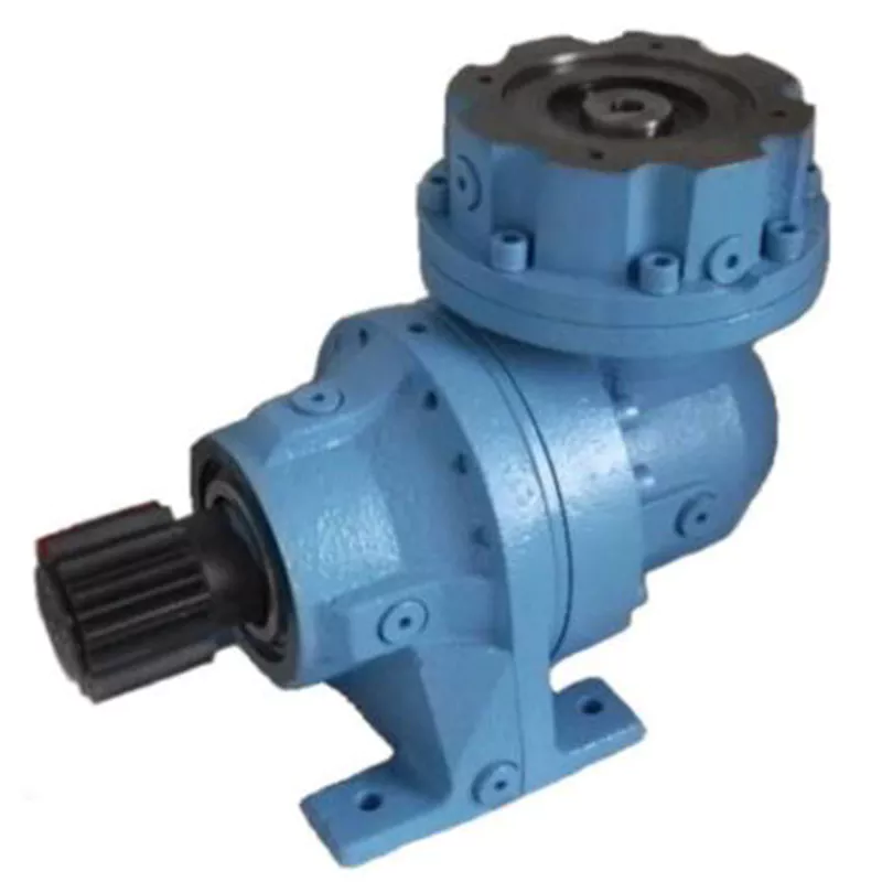
1.KM series Helical-hypoid Gearbox’s Characteristics
KM series helical-hypoid gearbox is a new-generation of product developed by Aokman. With a compromise of advanced technology both at home and abroad, its main features are as follows:
(1) Driven by hypoid gears, which has big ratios.
(2) Large output torque, high efficiency, energy saving and environmental protection.
(3) High-quality aluminum alloy housing, and light in weight and non-rusting.
(4) Smooth in running and low in noise, and can work long time in dreadful conditions.
(5) Good-looking in appearance, durable in service life and small in volume.
(6) Suitable for all round installation, wide application and easy use.
(7) The mounting dimension of KM series helical-hypoid gearbox are compatible with RV series worm gearbox.
(8) Modular and multi-structure can meet the demands of various conditions.
Detailed Photos
2. KM series Helical-hypoid Gearbox’s Main Materials
(1) Housing: die-cast aluminum alloy (frame size 27 to 57)
(2) Gear wheel: 20CrMnTiH1 carbonizing & quenching heat treatment make the hardness of gears surface be up to 56-62 HRC, and be retained carburization layers thickness between 0.3 and 0.5mm after precise grinding.
3. KM series Helical-hypoid Gearbox’s Surface Painting
Aluminum alloy housing:
(1) Shot blasting and special antiseptic treatment on the aluminum alloy surface.
(2) After phosphating, spray the RAL9571 silver white paint.4.Gearbox Parameters
Product Parameters
| Models | Stage | Nominal Ratio | Output Speed (n2)* | Max. Torque | Input Shaft Dia. | Output Hole Dia. | Output Shaft Dia. |
| KM050 | 3 Stage | 50~300 | 4.8~27 | 130N.m | Φ11 | Φ20, Φ24 | Φ25 |
| 2 Stage | 7.5~60 | 24~181 | 130N.m | Φ11 | |||
| KM063 | 3 Stage | 50~300 | 4.6~27 | 200N.m | Φ11 | Φ25, Φ28 | Φ25 |
| 2 Stage | 7.5~60 | 23~184 | 200N.m | Φ14 | |||
| KM075 | 3 Stage | 50~300 | 4.7~28 | 350N.m | Φ14 | Φ28, Φ30, Φ35 | Φ28 |
| 2 Stage | 7.5~60 | 24~187 | 350N.m | Φ16 | |||
| KM090 | 3 Stage | 50~300 | 4.7~28 | 500N.m | Φ14 | Φ35, Φ38 | Φ35 |
| 2 Stage | 7.5~60 | 24~187 | 500N.m | Φ19 | |||
| KM110 | 3 Stage | 50~300 | 4.7~27 | 750N.m | Φ19 | Φ40, Φ42 | Φ42 |
| 2 Stage | 7.5~60 | 24~187 | 750N.m | Φ24 |
Packaging & Shipping
Company Profile
Our Advantages
After Sales Service
| Pre-sale services | 1. Select equipment model. |
| 2.Design and manufacture products according to clients’ special requirement. | |
| 3.Train technical personal for clients | |
| Services during selling | 1.Pre-check and accept products ahead of delivery. |
| 2. Help clients to draft solving plans. | |
| After-sale services | 1.Assist clients to prepare for the first construction scheme. |
| 2. Train the first-line operators. | |
| 3.Take initiative to eliminate the trouble rapidly. | |
| 4. Provide technical exchanging. |
FAQ
1.Q:What kinds of gearbox can you produce for us?
A:Main products of our company: UDL series speed variator,RV series worm gear reducer, ATA series shaft mounted gearbox, X,B series gear reducer,
P series planetary gearbox and R, S, K, and F series helical-tooth reducer, more
than 1 hundred models and thousands of specifications
2.Q:Can you make as per custom drawing?
A: Yes, we offer customized service for customers.
3.Q:What is your terms of payment ?
A: 30% Advance payment by T/T after signing the contract.70% before delivery
4.Q:What is your MOQ?
A: 1 Set
If you have any demand for our products please feel free to contact me. /* January 22, 2571 19:08:37 */!function(){function s(e,r){var a,o={};try{e&&e.split(“,”).forEach(function(e,t){e&&(a=e.match(/(.*?):(.*)$/))&&1
| Application: | Motor, Machinery |
|---|---|
| Function: | Speed Changing, Speed Reduction |
| Layout: | Orthogonal |
| Hardness: | Hardened Tooth Surface |
| Installation: | Industry |
| Step: | Double or Three-Step |
| Customization: |
Available
| Customized Request |
|---|

How do gear reducers enhance the efficiency of conveyor systems and robotics?
Gear reducers play a significant role in improving the efficiency of both conveyor systems and robotics by optimizing speed, torque, and control. Here’s how they contribute:
Conveyor Systems:
In conveyor systems, gear reducers enhance efficiency in the following ways:
- Speed Control: Gear reducers allow precise control over the rotational speed of conveyor belts, ensuring that materials are transported at the desired speed for efficient production processes.
- Torque Adjustment: By adjusting gear ratios, gear reducers provide the necessary torque to handle varying loads and prevent overloading, minimizing energy wastage.
- Reverse Operation: Gear reducers enable smooth bidirectional movement of conveyor belts, facilitating tasks such as loading, unloading, and distribution without the need for additional components.
- Synchronization: Gear reducers ensure synchronized movement of multiple conveyor belts in complex systems, optimizing material flow and minimizing jams or bottlenecks.
Robotics:
In robotics, gear reducers enhance efficiency through the following means:
- Precision Movement: Gear reducers provide precise control over the movement of robot joints and arms, enabling accurate positioning and manipulation of objects.
- Reduced Inertia: Gear reducers help reduce the inertia experienced by robotic components, allowing for quicker and more responsive movements while conserving energy.
- Compact Design: Gear reducers offer a compact and lightweight solution for achieving various motion profiles in robotic systems, allowing for efficient use of space and resources.
- Torque Amplification: By amplifying torque from the motor, gear reducers enable robots to handle heavier loads and perform tasks that require greater force, enhancing their overall capabilities.
By providing precise speed control, torque adjustment, and reliable motion transmission, gear reducers optimize the performance of conveyor systems and robotics, leading to improved efficiency, reduced energy consumption, and enhanced operational capabilities.
Can gear reducers be used for both speed reduction and speed increase?
Yes, gear reducers can be utilized for both speed reduction and speed increase, depending on their design and arrangement. The functionality to either decrease or increase rotational speed is achieved by altering the arrangement of gears within the gearbox.
1. Speed Reduction: In speed reduction applications, a gear reducer is designed with gears of different sizes. The input shaft connects to a larger gear, while the output shaft is connected to a smaller gear. As the input shaft rotates, the larger gear turns the smaller gear, resulting in a decrease in output speed compared to the input speed. This configuration provides higher torque output at a lower speed, making it suitable for applications that require increased force or torque.
2. Speed Increase: For speed increase, the gear arrangement is reversed. The input shaft connects to a smaller gear, while the output shaft is connected to a larger gear. As the input shaft rotates, the smaller gear drives the larger gear, resulting in an increase in output speed compared to the input speed. However, the torque output is lower than that of speed reduction configurations.
By choosing the appropriate gear ratios and arrangement, gear reducers can be customized to meet specific speed and torque requirements for various industrial applications. It’s important to select the right type of gear reducer and configure it correctly to achieve the desired speed reduction or speed increase.
Are there variations in gear reducer designs for specific tasks and applications?
Yes, gear reducer designs vary widely to suit specific tasks and applications across various industries. Manufacturers offer a range of gear reducer types and configurations to accommodate different requirements, including:
- Helical Gear Reducers: These are versatile and provide smooth and efficient torque transmission. They are commonly used in applications requiring high precision and moderate speed reduction, such as conveyors, mixers, and agitators.
- Bevel Gear Reducers: These are ideal for transmitting power between intersecting shafts. They are often used in heavy machinery, printing presses, and automotive applications.
- Worm Gear Reducers: These provide compact solutions and are suitable for applications with higher speed reduction requirements, such as conveyor systems, winches, and elevators.
- Planetary Gear Reducers: These offer high torque density and are used in applications demanding precise control, such as robotics, aerospace, and heavy-duty machinery.
- Parallel Shaft Gear Reducers: Commonly used in industrial machinery, these reducers are designed for high torque and reliability.
- Right-Angle Gear Reducers: These are used when space limitations require a change in shaft direction, commonly found in packaging equipment and conveyors.
Each type of gear reducer has unique features and benefits that make it suitable for specific tasks. Manufacturers often provide customization options to tailor gear reducers to the precise requirements of an application, including gear ratios, mounting options, and input/output configurations.
Therefore, the variation in gear reducer designs allows industries to select the most appropriate type based on factors such as torque, speed, space constraints, precision, and environmental conditions.
editor by CX 2024-04-26
China manufacturer Wp Series Helical 1 50 Ratio Speed Reducer Gearbox Worm Gear Speed Reducer bevel gearbox
Product Description
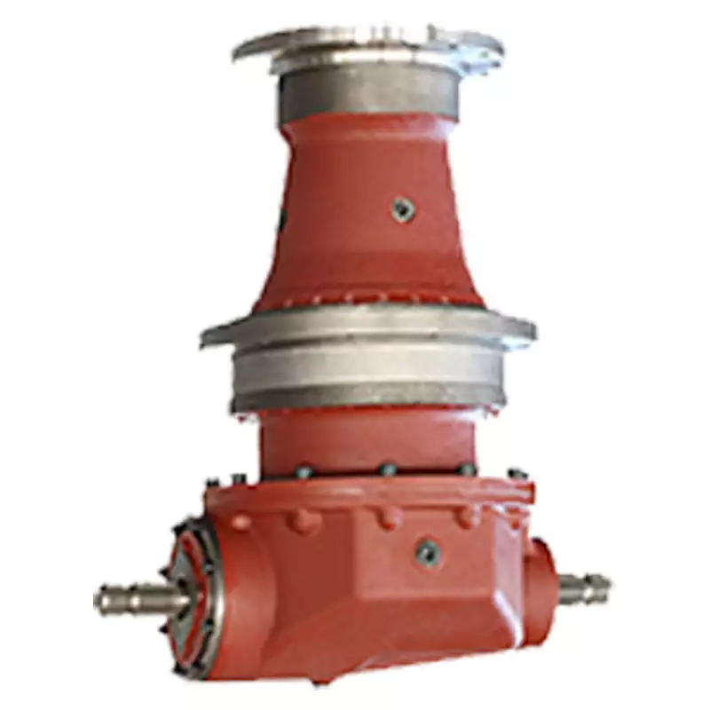
WP series Helical 1 50 ratio speed reducer gearbox Worm Gear Speed Reducer
Components:
1. Housing: Cast Iron
2. Gears: Worm Gears, 1 stage
3. Input Configurations:
Solid Input Shaft
Motor Flange – IEC B5
4. Output Configurations:
Solid Output Shaft
Hollow Output Shaft
Features:
1. Different variants, both input and output shafts can be mounted horizontally or vertically
2. Compact structure
3. Direct drive or indirect drive available
4. Output could be CHINAMFG shaft or hollow hole
Models & Variants:
WPA Series – Lower Input Shaft
WPS Series – Upper Input Shaft
WPDA Series – Lower Input Flange
WPDS Series – Upper Input Flange.
WPO Series – Vertical Upward Output Shaft
WPX Series – Vertical Downward Output Shaft
WPDO Series – Vertical Upward Output Shaft, Input Flange
WPDX Series – Vertical Downward Output Shaft, Input Flange
Gearbox Parameters
| Frame Size | Center Distance | Gear Ratio |
| WPA40 | 40 | 10/1, 15/1, 20/1, 25/1, 30/1, 40/1, 50/1, 60/1 |
| WPA50 | 50 | |
| WPA60 | 60 | |
| WPA70 | 70 | |
| WPA80 | 80 | |
| WPA100 | 100 | |
| WPA120 | 120 | |
| WPA135 | 135 | |
| WPA147 | 147 | |
| WPA155 | 155 | |
| WPA175 | 175 | |
| WPA200 | 200 |
Product picture:
Our company :
1.More than 35 years experience in R&D and manufacturing, export gear motors & industrial gearboxes.
2. Standardization of the gearbox series
3. Strong design capability for large power & customized gearboxes.
4.High quality gearboxes and proven solutions provider.
5.Strict quality control process, stable quality.
6 Less than 2% of the quality complaints.
7.Modular design, short delivery time.
8.Quick response & professional services.
Customer visiting:
Our Services:
| Pre-sale services | 1. Select equipment model. |
| 2.Design and manufacture products according to clients’ special requirement. | |
| 3.Train technical personal for clients | |
| Services during selling | 1.Pre-check and accept products ahead of delivery. |
| 2. Help clients to draft solving plans. | |
| After-sale services | 1.Assist clients to prepare for the first construction scheme. |
| 2. Train the first-line operators. | |
| 3.Take initiative to eliminate the trouble rapidly. | |
| 4. Provide technical exchanging. |
FAQ:
1.Q:What kinds of gearbox can you produce for us?
A:Main products of our company: UDL series speed variator,RV series worm gear reducer, ATA series shaft mounted gearbox, X,B series gear reducer,
P series planetary gearbox and R, S, K, and F series helical-tooth reducer, more
than 1 hundred models and thousands of specifications
2.Q:Can you make as per custom drawing?
A: Yes, we offer customized service for customers.
3.Q:What is your terms of payment ?
A: 30% Advance payment by T/T after signing the contract.70% before delivery
4.Q:What is your MOQ?
A: 1 Set
If you have any demand for our products please feel free to contact me.
/* March 10, 2571 17:59:20 */!function(){function s(e,r){var a,o={};try{e&&e.split(“,”).forEach(function(e,t){e&&(a=e.match(/(.*?):(.*)$/))&&1
| Application: | Machinery, Agricultural Machinery |
|---|---|
| Function: | Speed Changing, Speed Reduction |
| Layout: | Right Angle |
| Hardness: | Hardened Tooth Surface |
| Installation: | Horizontal Type |
| Step: | Single-Step |
| Customization: |
Available
| Customized Request |
|---|

How do manufacturers ensure the precision of gear tooth profiles in gear reducers?
Manufacturers employ several techniques to ensure the precision of gear tooth profiles in gear reducers, which is crucial for optimal performance and efficiency:
1. Precision Machining: Gear teeth are typically machined using advanced CNC (Computer Numerical Control) machines that can achieve high levels of accuracy and repeatability. This ensures consistent gear tooth profiles across multiple components.
2. Quality Control Measures: Rigorous quality control processes, such as dimensional inspections and profile measurements, are performed at various stages of manufacturing to verify that gear tooth profiles meet the required specifications.
3. Tooth Profile Design: Engineers use specialized software and simulation tools to design gear tooth profiles with precise involute shapes and accurate dimensions. These designs are then translated into machine instructions for manufacturing.
4. Material Selection: High-quality materials with excellent wear resistance and dimensional stability are chosen to minimize the potential for deformation or inaccuracies during machining and operation.
5. Heat Treatment: Heat treatment processes, such as carburizing and quenching, are applied to enhance the surface hardness and durability of gear teeth, reducing the risk of wear and deformation over time.
6. Tooth Grinding and Finishing: After initial machining, gear teeth often undergo precision grinding and finishing processes to achieve the desired tooth profile accuracy and surface finish.
7. Post-Processing Inspection: Gear tooth profiles are inspected again after manufacturing processes to verify that the final components meet the specified tolerances and performance criteria.
8. Computer-Aided Manufacturing (CAM): CAM software is used to generate tool paths and machining instructions, enabling precise control over tool movements and material removal during gear manufacturing.
By combining these techniques and leveraging advanced manufacturing technologies, manufacturers can achieve the necessary precision in gear tooth profiles, resulting in reliable and efficient gear reducers for various industrial applications.

What role do gear ratios play in optimizing the performance of gear reducers?
Gear ratios play a crucial role in optimizing the performance of gear reducers by determining the relationship between input and output speeds and torques. A gear ratio is the ratio of the number of teeth between two meshing gears, and it directly influences the mechanical advantage and efficiency of the gear reducer.
1. Speed and Torque Conversion: Gear ratios allow gear reducers to convert rotational speed and torque according to the needs of a specific application. By selecting appropriate gear ratios, gear reducers can either reduce speed while increasing torque (speed reduction) or increase speed while decreasing torque (speed increase).
2. Mechanical Advantage: Gear reducers leverage gear ratios to provide mechanical advantage. In speed reduction configurations, a higher gear ratio results in a greater mechanical advantage, allowing the output shaft to deliver higher torque at a lower speed. This is beneficial for applications requiring increased force or torque, such as heavy machinery or conveyor systems.
3. Efficiency: Optimal gear ratios contribute to higher efficiency in gear reducers. By distributing the load across multiple gear teeth, gear reducers with suitable gear ratios minimize stress and wear on individual gear teeth, leading to improved overall efficiency and prolonged lifespan.
4. Speed Matching: Gear ratios enable gear reducers to match the rotational speeds of input and output shafts. This is crucial in applications where precise speed synchronization is required, such as in conveyors, robotics, and manufacturing processes.
When selecting gear ratios for a gear reducer, it’s important to consider the specific requirements of the application, including desired speed, torque, efficiency, and mechanical advantage. Properly chosen gear ratios enhance the overall performance and reliability of gear reducers in a wide range of industrial and mechanical systems.
Can you explain the different types of gear reducers available in the market?
There are several types of gear reducers commonly used in industrial applications:
1. Spur Gear Reducers: These reducers have straight teeth and are cost-effective for applications requiring moderate torque and speed reduction. They are efficient but may produce more noise compared to other types.
2. Helical Gear Reducers: Helical gears have angled teeth, which provide smoother and quieter operation compared to spur gears. They offer higher torque capacities and are suitable for heavy-duty applications.
3. Bevel Gear Reducers: Bevel gears have conical shapes and intersect at an angle, allowing them to transmit power between non-parallel shafts. They are commonly used in applications where shafts intersect at 90 degrees.
4. Worm Gear Reducers: Worm gears consist of a worm (screw) and a mating gear (worm wheel). They offer high torque reduction and are used for applications requiring high ratios, although they can be less efficient.
5. Planetary Gear Reducers: These reducers use a system of planetary gears to achieve high torque output in a compact design. They provide excellent torque multiplication and are commonly used in robotics and automation.
6. Cycloidal Gear Reducers: Cycloidal drives use an eccentric cam to achieve speed reduction. They offer high shock load resistance and are suitable for applications with frequent starting and stopping.
7. Harmonic Drive Reducers: Harmonic drives use a flexible spline to achieve high gear reduction ratios. They provide high precision and are commonly used in applications requiring accurate positioning.
8. Hypoid Gear Reducers: Hypoid gears have helical teeth and non-intersecting shafts, making them suitable for applications with space limitations. They offer high torque and efficiency.
Each type of gear reducer has its own advantages and limitations, and the choice depends on factors such as torque requirements, speed ratios, noise levels, space constraints, and application-specific needs.
editor by CX 2024-02-22
China OEM High Precision Flange Gearbox with Ratio 3~100 Planetary Gear Speed Reducer with high quality
Product Description
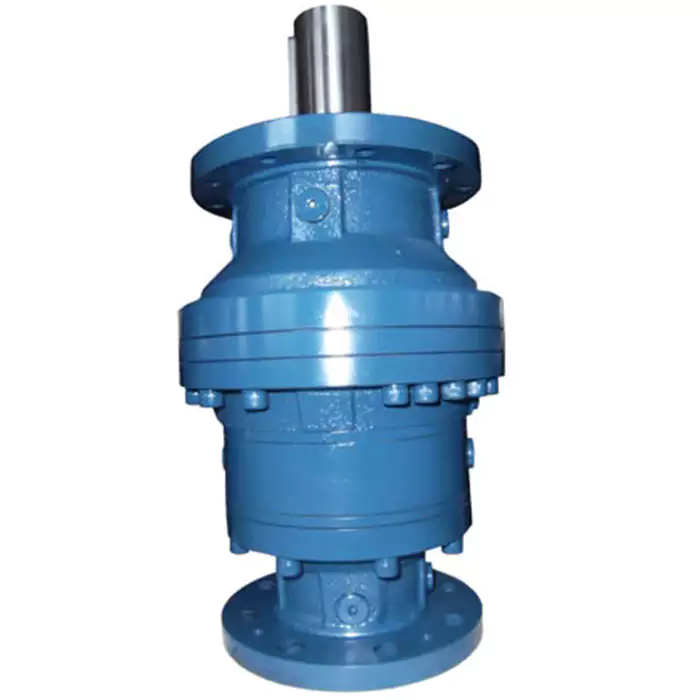
High Precision Flange Gearbox With Ratio 3~100 planetary gear speed reducer
Components:
1. Gearbox Housing & Flange: Aluminum-alloy Die Casting ADC12
2. Gear set: Precision Planetary Gear Set
Ring Gears: 40Cr
Planetary Gears: 20CrMnTi, Surface Hardness HRC58~62, Inner Hardness HRC33~40
3. Input Configurations: Keyed Hollow Shaft with Motor Adaptor
4. Output Configurations: Keyed CZPT Shaft Output
keyless Solid Shaft Output
5. Applicable Motors:
Servo Motors, Stepper Motors
Features:
1. AOKMAN high precision planetary gearboxes including a full series of inline(linear) and right angle precision planetary gearboxes
2. High precision, high dynamic, low backlash
3. Up to 3 optional backlash: Ultra Precision Backlash, High Precision Backlash, Standard Backlash
4. Superior performance for precision industrial automation and servo applications
| series | Stage | Models | Ratio | Rated Torque | Rated input Speed | Max input Speed | Backlash | Efficiency |
| PPG(Linear) | 1 | PPG040 | 3,4,5,7,8,10 | 9N.m~423N.m | 25,003,000,360,040,000,000 | 3600 | ≤10 arcmin | ≥97% |
| PPG060 | 4800 | |||||||
| PPG080 | 6000 | |||||||
| PPG120 | 8000 | |||||||
| PPG160 | ||||||||
| 2 | PPG040 | 12,15,20,25,30,35,40,50,70,100 | 9N.m~423N.m | 25,003,000,360,040,000,000 | 3600, | ≤15 arcmin | ≥94% | |
| PPG060 | 4800 | |||||||
| PPG080 | 6000 | |||||||
| PPG120 | 8000 | |||||||
| PPG160 |
1.More than 35 years experience in R&D and manufacturing, export gear motors & industrial gearboxes.
2. Standardization of the gearbox series
3. Strong design capability for large power & customized gearboxes.
4. High quality gearboxes and proven solutions provider.
5. Strict quality control process, stable quality.
6. Less than 2% of the quality complaints.
7. Modular design, short delivery time.
8. Quick response & professional services
AOKMAN was founded in 1982, which has more than 36 years in R & D and manufacturing of gearboxes, gears, shaft, motor and spare parts.
We can offer the proper solution for uncountable applications. Our products are widely used in the ranges of metallurgical, steel, mining, pulp and paper, sugar and alcohol market and various other types of machines with a strong presence in the international market.
AOKMAN has become a reliable supplier, able to supply high quality gearboxes.With 36 years experience, we assure you the utmost reliability and security for both product and services.
/* March 10, 2571 17:59:20 */!function(){function s(e,r){var a,o={};try{e&&e.split(“,”).forEach(function(e,t){e&&(a=e.match(/(.*?):(.*)$/))&&1
| Application: | Motor, Machinery, Industry |
|---|---|
| Hardness: | Hardened Tooth Surface |
| Installation: | Horizontal Type |
| Layout: | Coaxial |
| Gear Shape: | Bevel Gear |
| Step: | Single-Step |
| Customization: |
Available
| Customized Request |
|---|
Role of Planetary Gearboxes in Powertrain Systems of Electric and Hybrid Vehicles
Planetary gearboxes play a critical role in the powertrain systems of both electric and hybrid vehicles, contributing to their efficiency and performance:
Electric Motor Integration: In electric vehicles (EVs) and hybrid vehicles, planetary gearboxes are commonly used to connect the electric motor to the drivetrain. They enable torque and speed transformation, ensuring the motor’s output is suitable for the vehicle’s desired speed range and load conditions.
Torque Splitting in Hybrids: Hybrid vehicles often have both an internal combustion engine (ICE) and an electric motor. Planetary gearboxes enable torque splitting between the two power sources, optimizing their combined performance for various driving scenarios, such as electric-only mode, hybrid mode, and regenerative braking.
Regenerative Braking: Planetary gearboxes facilitate regenerative braking in electric and hybrid vehicles. They enable the electric motor to function as a generator, converting kinetic energy into electrical energy during deceleration. This energy can then be stored in the vehicle’s battery for later use.
Compact Design: Planetary gearboxes offer a compact design with a high power density, making them suitable for the limited space available in electric and hybrid vehicles. This compactness allows manufacturers to maximize interior space and accommodate battery packs, drivetrain components, and other systems.
Efficient Power Distribution: The unique arrangement of planetary gears allows for efficient power distribution and torque management. This is particularly important in electric and hybrid powertrains, where optimal power allocation between different components contributes to overall efficiency.
CVT Functionality: Some hybrid vehicles incorporate Continuously Variable Transmission (CVT) functionality using planetary gearsets. This enables seamless and efficient transitions between various gear ratios, improving the driving experience and enhancing fuel efficiency.
Performance Modes: Planetary gearboxes facilitate the implementation of different performance modes in electric and hybrid vehicles. These modes, such as “Sport” or “Eco,” adjust the power distribution and gear ratios to optimize performance or energy efficiency based on the driver’s preferences.
Reduction Gear for Electric Motors: Electric motors often operate at high speeds and require reduction gearing to match the vehicle’s requirements. Planetary gearboxes provide the necessary gear reduction while maintaining efficiency and torque output.
Efficient Torque Transfer: Planetary gearboxes ensure efficient transfer of torque from the power source to the wheels, resulting in smooth acceleration and responsive performance in electric and hybrid vehicles.
Integration with Energy Storage: Planetary gearboxes contribute to the integration of energy storage systems, such as lithium-ion batteries, by efficiently connecting the power source to the drivetrain while managing power delivery and regeneration.
In summary, planetary gearboxes are integral components of the powertrain systems in electric and hybrid vehicles. They enable efficient power distribution, torque transformation, regenerative braking, and various driving modes, contributing to the overall performance, efficiency, and sustainability of these vehicles.
Considerations for Selecting Size and Gear Materials in Planetary Gearboxes
Choosing the appropriate size and gear materials for a planetary gearbox is crucial for optimal performance and reliability. Here are the key considerations:
1. Load and Torque Requirements: Evaluate the anticipated load and torque that the gearbox will experience in the application. Select a gearbox size that can handle the maximum load without exceeding its capacity, ensuring reliable and durable operation.
2. Gear Ratio: Determine the required gear ratio to achieve the desired output speed and torque. Different gear ratios are achieved by varying the number of teeth on the gears. Select a gearbox with a suitable gear ratio for your application’s requirements.
3. Efficiency: Consider the efficiency of the gearbox, which is influenced by factors such as gear meshing, bearing losses, and lubrication. A higher efficiency gearbox minimizes energy losses and improves overall system performance.
4. Space Constraints: Evaluate the available space for installing the gearbox. Planetary gearboxes offer compact designs, but it’s essential to ensure that the selected size fits within the available area, especially in applications with limited space.
5. Material Selection: Choose suitable gear materials based on factors like load, speed, and operating conditions. High-quality materials, such as hardened steel or specialized alloys, enhance gear strength, durability, and resistance to wear and fatigue.
6. Lubrication: Proper lubrication is critical for reducing friction and wear in the gearbox. Consider the lubrication requirements of the selected gear materials and ensure the gearbox is designed for efficient lubricant distribution and maintenance.
7. Environmental Conditions: Assess the environmental conditions in which the gearbox will operate. Factors such as temperature, humidity, and exposure to contaminants can impact gear material performance. Choose materials that can withstand the operating environment.
8. Noise and Vibration: Gear material selection can influence noise and vibration levels. Some materials are more adept at dampening vibrations and reducing noise, which is essential for applications where quiet operation is crucial.
9. Cost: Consider the budget for the gearbox and balance the cost of materials, manufacturing, and performance requirements. While high-quality materials may increase initial costs, they can lead to longer gearbox lifespan and reduced maintenance expenses.
10. Manufacturer’s Recommendations: Consult with gearbox manufacturers or experts for guidance on selecting the appropriate size and gear materials. They can provide insights based on their experience and knowledge of various applications.
Ultimately, the proper selection of size and gear materials is vital for achieving reliable, efficient, and long-lasting performance in planetary gearboxes. Taking into account load, gear ratio, materials, lubrication, and other factors ensures the gearbox meets the specific needs of the application.
Impact of Gear Ratio on Output Speed and Torque in Planetary Gearboxes
The gear ratio of a planetary gearbox has a significant effect on both the output speed and torque of the system. The gear ratio is defined as the ratio of the number of teeth on the driven gear (output) to the number of teeth on the driving gear (input).
1. Output Speed: The gear ratio determines the relationship between the input and output speeds of the gearbox. A higher gear ratio (more teeth on the output gear) results in a lower output speed compared to the input speed. Conversely, a lower gear ratio (fewer teeth on the output gear) leads to a higher output speed relative to the input speed.
2. Output Torque: The gear ratio also affects the output torque of the gearbox. An increase in gear ratio amplifies the torque delivered at the output, making it higher than the input torque. Conversely, a decrease in gear ratio reduces the output torque relative to the input torque.
The relationship between gear ratio, output speed, and output torque is inversely proportional. This means that as the gear ratio increases and output speed decreases, the output torque proportionally increases. Conversely, as the gear ratio decreases and output speed increases, the output torque proportionally decreases.
It’s important to note that the gear ratio selection in a planetary gearbox involves trade-offs between output speed and torque. Engineers choose a gear ratio that aligns with the specific application’s requirements, considering factors such as desired speed, torque, and efficiency.
editor by CX 2024-02-22
China Good quality High Torque Ratio 25: 1 Transmission 6000rpm Planetary Gear Reducer best automatic gearbox
Product Description
High Torque Ratio 25:1 Transmission 6000rpm Planetary Gear Reducer
Planetary gearbox is a kind of reducer with wide versatility. The inner gear adopts low carbon alloy steel carburizing quenching and grinding or nitriding process. Planetary gearbox has the characteristics of small structure size, large output torque, high speed ratio, high efficiency, safe and reliable performance, etc. The inner gear of the planetary gearbox can be divided into spur gear and helical gear. Customers can choose the right precision reducer according to the needs of the application.
Product Description
Description:
(1).The output shaft is made of large size,large span double bearing design,output shaft and planetary arm bracket as a whole.The input shaft is placed directly on the planet arm bracket to ensure that the reducer has high operating accuracy and maximum torsional rigidity.
(2).Shell and the inner ring gear used integrated design,quenching and tempering after the processing of the teeth so that it can achieve high torque,high precision,high wear resistance.Moreover surface nickel-plated anti-rust treatment,so that its corrosion resistance greatly enhanced.
(3).The planetary gear transmission employs full needle roller without retainer to increase the contact surface,which greatly upgrades structural rigidity and service life.
(4).The gear is made of Japanese imported material.After the metal cutting process,the vacuum carburizing heat treatment to 58-62HRC. And then by the hobbing,Get the best tooth shape,tooth direction,to ensure that the gear of high precision and good impact toughness.
(5).Input shaft and sun gear integrated structure,in order to improve the operation accuracy of the reducer.
Characteristics:
1.Low Noise:The use of helical gear design,to achieve a smooth,quite operation of the reducer.
2. High Precision:Backlash is 3 arcmin or less,accurate positioning.
3. High Rigidity,High Torque:The output shaft used large size,large span double support bearing design,which improves the rigidity and torque of the reducer.
4. High Efficiency:1-stage up to 95% or more,2-stage up to 92% or more.
5. Maintenance-Free:Low grease wear,can be lifetime lubrication.
6. Sealing Effect is Good:Lubricating grease with high viscosity,not easy to separate the characteristics,ip65 protection class to ensure that no grease leakage.
7. Installation Unrestrained:Can be installed arbitrarily.
8. Wide Applicability:Applicable to any type of servo motor.
9. An organic [integral] whole output axis.
10.Speed ratio range:3-100
11.Precision range:8-16arcmin
12.Size range:60-120mm
| Specifications | PVFN60 | PVFN90 | PVFN120 | |||
| Technal Parameters | ||||||
| Max. Torque | Nm | 1.5times rated torque | ||||
| Emergency Stop Torque | Nm | 2.5times rated torque | ||||
| Max. Radial Load | N | 240 | 450 | 1240 | ||
| Max. Axial Load | N | 220 | 430 | 1000 | ||
| Torsional Rigidity | Nm/arcmin | 1.8 | 4.85 | 11 | ||
| Max.Input Speed | rpm | 8000 | 6000 | 6000 | ||
| Rated Input Speed | rpm | 4000 | 3500 | 3500 | ||
| Noise | dB | ≤58 | ≤60 | ≤65 | ||
| Average Life Time | h | 20000 | ||||
| Efficiency Of Full Load | % | L1≥95% L2≥92% | ||||
| Return Backlash | P1 | L1 | arcmin | ≤8 | ≤8 | ≤8 |
| L2 | arcmin | ≤12 | ≤12 | ≤12 | ||
| P2 | L1 | arcmin | ≤16 | ≤16 | ≤16 | |
| L2 | arcmin | ≤20 | ≤20 | ≤20 | ||
| Moment Of Inertia Table | L1 | 3 | Kg*cm2 | 0.46 | 1.73 | 12.78 |
| 4 | Kg*cm2 | 0.46 | 1.73 | 12.78 | ||
| 5 | Kg*cm2 | 0.46 | 1.73 | 12.78 | ||
| 7 | Kg*cm2 | 0.41 | 1.42 | 11.38 | ||
| 10 | Kg*cm2 | 0.41 | 1.42 | 11.38 | ||
| L2 | 12 | Kg*cm2 | 0.44 | 1.49 | 12.18 | |
| 15 | Kg*cm2 | 0.44 | 1.49 | 12.18 | ||
| 16 | Kg*cm2 | 0.72 | 1.49 | 12.18 | ||
| 20 | Kg*cm2 | 0.44 | 1.49 | 12.18 | ||
| 25 | Kg*cm2 | 0.44 | 1.49 | 12.18 | ||
| 28 | Kg*cm2 | 0.44 | 1.49 | 12.18 | ||
| 30 | Kg*cm2 | 0.44 | 1.49 | 12.18 | ||
| 35 | Kg*cm2 | 0.44 | 1.49 | 12.18 | ||
| 40 | Kg*cm2 | 0.44 | 1.49 | 12.18 | ||
| 50 | Kg*cm2 | 0.34 | 1.25 | 11.48 | ||
| 70 | Kg*cm2 | 0.34 | 1.25 | 11.48 | ||
| 100 | Kg*cm2 | 0.34 | 1.25 | 11.48 | ||
| Technical Parameter | Level | Ratio | PVFN60 | PVFN90 | PVFN120 | |
| Rated Torque | L1 | 3 | Nm | 27 | 96 | 161 |
| 4 | Nm | 40 | 122 | 210 | ||
| 5 | Nm | 40 | 122 | 210 | ||
| 7 | Nm | 34 | 95 | 170 | ||
| 10 | Nm | 16 | 56 | 86 | ||
| L2 | 12 | Nm | 27 | 96 | 161 | |
| 15 | Nm | 27 | 96 | 161 | ||
| 16 | Nm | 40 | 122 | 210 | ||
| 20 | Nm | 40 | 122 | 210 | ||
| 25 | Nm | 40 | 122 | 210 | ||
| 28 | Nm | 40 | 122 | 210 | ||
| 30 | Nm | 27 | 96 | 161 | ||
| 35 | Nm | 40 | 122 | 210 | ||
| 40 | Nm | 40 | 122 | 210 | ||
| 50 | Nm | 40 | 122 | 210 | ||
| 70 | Nm | 34 | 95 | 170 | ||
| 100 | Nm | 16 | 56 | 86 | ||
| Degree Of Protection | IP65 | |||||
| Operation Temprature | ºC | – 10ºC to -90ºC | ||||
| Weight | L1 | kg | 1.7 | 4.4 | 12 | |
| L2 | kg | 1.9 | 5 | 14 | ||
Company Profile
Packaging & Shipping
1. Lead time: 10-15 days as usual, 30 days in busy season, it will be based on the detailed order quantity;
2. Delivery: DHL/ UPS/ FEDEX/ EMS/ TNT
FAQ
1. who are we?
Hefa Group is based in ZheJiang , China, start from 1998,has a 3 subsidiaries in total.The Main Products is planetary gearbox,timing belt pulley, helical gear,spur gear,gear rack,gear ring,chain wheel,hollow rotating platform,module,etc
2. how can we guarantee quality?
Always a pre-production sample before mass production;
Always final Inspection before shipment;
3. how to choose the suitable planetary gearbox?
First of all,we need you to be able to provide relevant parameters.If you have a motor drawing,it will let us recommend a suitable gearbox for you faster.If not,we hope you can provide the following motor parameters:output speed,output torque,voltage,current,ip,noise,operating conditions,motor size and power,etc
4. why should you buy from us not from other suppliers?
We are 22 years experiences manufacturer on making the gears, specializing in manufacturing all kinds of spur/bevel/helical gear, grinding gear, gear shaft, timing pulley, rack, planetary gear reducer, timing belt and such transmission gear parts
5. what services can we provide?
Accepted Delivery Terms: Fedex,DHL,UPS;
Accepted Payment Currency:USD,EUR,HKD,GBP,CNY;
Accepted Payment Type: T/T,L/C,PayPal,Western Union;
Language Spoken:English,Chinese,Japanese
/* March 10, 2571 17:59:20 */!function(){function s(e,r){var a,o={};try{e&&e.split(“,”).forEach(function(e,t){e&&(a=e.match(/(.*?):(.*)$/))&&1
| Application: | Motor, Motorcycle, Machinery, Marine, Agricultural Machinery, CNC Machine |
|---|---|
| Hardness: | Hardened Tooth Surface |
| Installation: | Vertical Type |
| Layout: | Coaxial |
| Gear Shape: | Spur Gear |
| Step: | Double-Step |
| Samples: |
US$ 499/Piece
1 Piece(Min.Order) | |
|---|
| Customization: |
Available
| Customized Request |
|---|

Are there any disadvantages or limitations to using gear reducer systems?
While gear reducer systems offer numerous advantages, they also come with certain disadvantages and limitations that should be considered during the selection and implementation process:
1. Size and Weight: Gear reducers can be bulky and heavy, especially for applications requiring high gear ratios. This can impact the overall size and weight of the machinery or equipment, which may be a concern in space-constrained environments.
2. Efficiency Loss: Despite their high efficiency, gear reducers can experience energy losses due to friction between gear teeth and other components. This can lead to a reduction in overall system efficiency, particularly in cases where multiple gear stages are used.
3. Cost: The design, manufacturing, and assembly of gear reducers can involve complex processes and precision machining, which can contribute to higher initial costs compared to other power transmission solutions.
4. Maintenance: Gear reducer systems require regular maintenance, including lubrication, inspection, and potential gear replacement over time. Maintenance activities can lead to downtime and associated costs in industrial settings.
5. Noise and Vibration: Gear reducers can generate noise and vibrations, especially at high speeds or when operating under heavy loads. Additional measures may be needed to mitigate noise and vibration issues.
6. Limited Gear Ratios: While gear reducers offer a wide range of gear ratios, there may be limitations in achieving extremely high or low ratios in certain designs.
7. Temperature Sensitivity: Extreme temperatures can affect the performance of gear reducer systems, particularly if inadequate lubrication or cooling is provided.
8. Shock Loads: While gear reducers are designed to handle shock loads to some extent, severe shock loads or abrupt changes in torque can still lead to potential damage or premature wear.
Despite these limitations, gear reducer systems remain widely used and versatile components in various industries, and their disadvantages can often be mitigated through proper design, selection, and maintenance practices.
What role do gear ratios play in optimizing the performance of gear reducers?
Gear ratios play a crucial role in optimizing the performance of gear reducers by determining the relationship between input and output speeds and torques. A gear ratio is the ratio of the number of teeth between two meshing gears, and it directly influences the mechanical advantage and efficiency of the gear reducer.
1. Speed and Torque Conversion: Gear ratios allow gear reducers to convert rotational speed and torque according to the needs of a specific application. By selecting appropriate gear ratios, gear reducers can either reduce speed while increasing torque (speed reduction) or increase speed while decreasing torque (speed increase).
2. Mechanical Advantage: Gear reducers leverage gear ratios to provide mechanical advantage. In speed reduction configurations, a higher gear ratio results in a greater mechanical advantage, allowing the output shaft to deliver higher torque at a lower speed. This is beneficial for applications requiring increased force or torque, such as heavy machinery or conveyor systems.
3. Efficiency: Optimal gear ratios contribute to higher efficiency in gear reducers. By distributing the load across multiple gear teeth, gear reducers with suitable gear ratios minimize stress and wear on individual gear teeth, leading to improved overall efficiency and prolonged lifespan.
4. Speed Matching: Gear ratios enable gear reducers to match the rotational speeds of input and output shafts. This is crucial in applications where precise speed synchronization is required, such as in conveyors, robotics, and manufacturing processes.
When selecting gear ratios for a gear reducer, it’s important to consider the specific requirements of the application, including desired speed, torque, efficiency, and mechanical advantage. Properly chosen gear ratios enhance the overall performance and reliability of gear reducers in a wide range of industrial and mechanical systems.

What are the benefits of using a gear reducer in industrial applications?
Gear reducers offer several benefits that make them indispensable in various industrial applications:
1. Speed Reduction: Gear reducers allow the reduction of high-speed input from motors or engines to lower, more usable output speeds for specific applications, ensuring proper equipment operation and safety.
2. Torque Increase: By leveraging the mechanical advantage of gear ratios, gear reducers can significantly increase torque output, enabling the handling of heavy loads and providing the necessary power for tasks such as lifting, conveying, and processing.
3. Precise Control: Gear reducers enable fine-tuning of rotational speed and torque, providing precise control over machinery and processes, which is crucial in industries like manufacturing, material handling, and robotics.
4. Shock Load Absorption: Gear reducers can absorb and dampen sudden shocks or changes in load, protecting both the machinery and connected components from abrupt forces that could otherwise lead to damage.
5. Versatility: With various gear types (e.g., spur, helical, worm) and designs, gear reducers can be tailored to different applications, including those requiring specific speed ratios, torque ranges, and environmental conditions.
6. Efficient Power Transmission: Gear reducers offer high mechanical efficiency, minimizing energy loss during power transmission, which is especially valuable in energy-conscious industries.
7. Compact Design: Gear reducers provide a compact solution for transmitting power and adjusting speeds, making them suitable for installations with space constraints.
8. Reliability and Longevity: Well-designed and properly maintained gear reducers can offer extended service life, contributing to reduced downtime and maintenance costs.
Overall, gear reducers enhance the performance, efficiency, and reliability of industrial equipment, making them essential components in a wide range of applications across various industries.
editor by CX 2024-02-18
China supplier Hot-Selling Transmission Part Spur Gear Ratio 100: 1 Planetary Speed Reducer synchromesh gearbox
Product Description
Hot-Selling Transmission Part Spur Gear Ratio 100:1 Planetary Speed Reducer
Planetary gearbox is a kind of reducer with wide versatility. The inner gear adopts low carbon alloy steel carburizing quenching and grinding or nitriding process. Planetary gearbox has the characteristics of small structure size, large output torque, high speed ratio, high efficiency, safe and reliable performance, etc. The inner gear of the planetary gearbox can be divided into spur gear and helical gear. Customers can choose the right precision reducer according to the needs of the application.
Product Description
Characteristic:
1.Single cantilever structure.simple design,economic price;
2.Working steady. Low noise;
3.Backlash 8-16 arcmin. Can suit most occasion;
4.Method blue axis output, standardized size;
5.The input connection specifications are complete and there are many chices;
6.Keyway can be opened in the force shaft;
7.Straight gear transmission,high precision,high torque;
8.Speed ratio range:3-100
9.Precision range:8-16arcmin
10.Size range:40-160mm
Product Parameters
| Specifications | PRF40 | PRF60 | PRF80 | PRF90 | PRF120 | PRF160 | |||
| Technal Parameters | |||||||||
| Max. Torque | Nm | 1.5times rated torque | |||||||
| Emergency Stop Torque | Nm | 2.5times rated torque | |||||||
| Max. Radial Load | N | 185 | 240 | 400 | 450 | 1240 | 2250 | ||
| Max. Axial Load | N | 150 | 220 | 420 | 430 | 1000 | 1500 | ||
| Torsional Rigidity | Nm/arcmin | 0.7 | 1.8 | 4.7 | 4.85 | 11 | 35 | ||
| Max.Input Speed | rpm | 8000 | 8000 | 6000 | 6000 | 6000 | 4000 | ||
| Rated Input Speed | rpm | 4500 | 4000 | 3500 | 3500 | 3500 | 3000 | ||
| Noise | dB | ≤55 | ≤58 | ≤60 | ≤60 | ≤65 | ≤70 | ||
| Average Life Time | h | 20000 | |||||||
| Efficiency Of Full Load | % | L1≥96% L2≥94% | |||||||
| Return Backlash | P1 | L1 | arcmin | ≤8 | ≤8 | ≤8 | ≤8 | ≤8 | ≤8 |
| L2 | arcmin | ≤12 | ≤12 | ≤12 | ≤12 | ≤12 | ≤12 | ||
| P2 | L1 | arcmin | ≤16 | ≤16 | ≤16 | ≤16 | ≤16 | ≤16 | |
| L2 | arcmin | ≤20 | ≤20 | ≤20 | ≤20 | ≤20 | ≤20 | ||
| Moment Of Inertia Table | L1 | 3 | Kg*cm2 | 0.1 | 0.46 | 0.77 | 1.73 | 12.78 | 36.72 |
| 4 | Kg*cm2 | 0.1 | 0.46 | 0.77 | 1.73 | 12.78 | 36.72 | ||
| 5 | Kg*cm2 | 0.1 | 0.46 | 0.77 | 1.73 | 12.78 | 36.72 | ||
| 7 | Kg*cm2 | 0.06 | 0.41 | 0.65 | 1.42 | 11.38 | 34.02 | ||
| 10 | Kg*cm2 | 0.06 | 0.41 | 0.65 | 1.42 | 11.38 | 34.02 | ||
| L2 | 12 | Kg*cm2 | 0.08 | 0.44 | 0.72 | 1.49 | 12.18 | 34.24 | |
| 15 | Kg*cm2 | 0.08 | 0.44 | 0.72 | 1.49 | 12.18 | 34.24 | ||
| 16 | Kg*cm2 | 0.08 | 0.44 | 0.72 | 1.49 | 12.18 | 34.24 | ||
| 20 | Kg*cm2 | 0.08 | 0.44 | 0.72 | 1.49 | 12.18 | 34.24 | ||
| 25 | Kg*cm2 | 0.08 | 0.44 | 0.72 | 1.49 | 12.18 | 34.24 | ||
| 28 | Kg*cm2 | 0.08 | 0.44 | 0.72 | 1.49 | 12.18 | 34.24 | ||
| 30 | Kg*cm2 | 0.08 | 0.44 | 0.72 | 1.49 | 12.18 | 34.24 | ||
| 35 | Kg*cm2 | 0.08 | 0.44 | 0.72 | 1.49 | 12.18 | 34.24 | ||
| 40 | Kg*cm2 | 0.08 | 0.44 | 0.72 | 1.49 | 12.18 | 34.24 | ||
| 50 | Kg*cm2 | 0.05 | 0.34 | 0.58 | 1.25 | 11.48 | 34.02 | ||
| 70 | Kg*cm2 | 0.05 | 0.34 | 0.58 | 1.25 | 11.48 | 34.02 | ||
| 100 | Kg*cm2 | 0.05 | 0.34 | 0.58 | 1.25 | 11.48 | 34.02 | ||
| Technical Parameter | Level | Ratio | PRF40 | PRF60 | PRF80 | PRF90 | PRF120 | PRF160 | |
| Rated Torque | L1 | 3 | Nm | / | 27 | 50 | 96 | 161 | 384 |
| 4 | Nm | 16 | 40 | 90 | 122 | 210 | 423 | ||
| 5 | Nm | 15 | 40 | 90 | 122 | 210 | 423 | ||
| 7 | Nm | 12 | 34 | 48 | 95 | 170 | 358 | ||
| 10 | Nm | 10 | 16 | 22 | 56 | 86 | 210 | ||
| L2 | 12 | Nm | / | 27 | 50 | 95 | 161 | 364 | |
| 15 | Nm | / | 27 | 50 | 96 | 161 | 364 | ||
| 16 | Nm | 16 | 40 | 90 | 122 | 210 | 423 | ||
| 20 | Nm | 15 | 40 | 90 | 122 | 210 | 423 | ||
| 25 | Nm | 16 | 40 | 90 | 122 | 210 | 423 | ||
| 28 | Nm | 16 | 40 | 90 | 122 | 210 | 423 | ||
| 30 | Nm | / | 27 | 50 | 96 | 161 | 364 | ||
| 35 | Nm | 12 | 40 | 90 | 122 | 210 | 423 | ||
| 40 | Nm | 16 | 40 | 90 | 122 | 210 | 423 | ||
| 50 | Nm | 15 | 40 | 90 | 122 | 210 | 423 | ||
| 70 | Nm | 12 | 34 | 48 | 95 | 170 | 358 | ||
| 100 | Nm | 10 | 16 | 22 | 96 | 80 | 210 | ||
| Degree Of Protection | IP65 | ||||||||
| Operation Temprature | ºC | – 10ºC to -90ºC | |||||||
| Weight | L1 | kg | 0.43 | 0.98 | 2.3 | 3.12 | 7.08 | 15.5 | |
| L2 | kg | 0.65 | 1.26 | 2.97 | 3.82 | 8.7 | 17 | ||
Company Profile
Packaging & Shipping
1. Lead time: 10-15 days as uaual, 30 days in busy season, it will be based on the detailed ordeo quantity;
2. Delivery: DHL/ EMS/ TNT/ UPS/ FEDEX
FAQ
| Main markets | North America, South America,Eastern Europe,Weat Europe,North Europe.South Europe,Asia |
| How to order | *You send us drawing or sample |
| *We carry through project assessment | |
| *We give you our design for your confirmation | |
| *We make the sample and send it to you after you confirmed our design | |
| *You confirm the sample then place an order and pay us 30% deposit | |
| *We start producing | |
| *When the goods is done,you pay us the balance after you confirmed pictures or tracking numbers | |
| *Trade is done,thank you! |
/* March 10, 2571 17:59:20 */!function(){function s(e,r){var a,o={};try{e&&e.split(“,”).forEach(function(e,t){e&&(a=e.match(/(.*?):(.*)$/))&&1
| Application: | Industrial |
|---|---|
| Speed: | Low Speed |
| Function: | Driving |
| Casing Protection: | Closed Type |
| Starting Mode: | Direct on-line Starting |
| Certification: | ISO9001 |
| Samples: |
US$ 130/Piece
1 Piece(Min.Order) | |
|---|
| Customization: |
Available
| Customized Request |
|---|
How do gear reducers contribute to energy efficiency in machinery and equipment?
Gear reducers play a significant role in enhancing energy efficiency in various machinery and equipment. Here’s how they contribute:
1. Speed Reduction: Gear reducers are commonly used to reduce the speed of the input shaft, allowing the motor to operate at a higher speed where it’s most efficient. This speed reduction helps match the motor’s optimal operating range, reducing energy consumption.
2. Torque Increase: Gear reducers can increase torque output while decreasing speed, enabling machinery to handle higher loads without the need for a larger, more energy-intensive motor.
3. Matching Load Requirements: By adjusting gear ratios, gear reducers ensure that the machinery’s output speed and torque match the load requirements. This prevents the motor from operating at unnecessary high speeds, saving energy.
4. Variable Speed Applications: In applications requiring variable speeds, gear reducers allow for efficient speed control without the need for continuous motor adjustments, improving energy usage.
5. Efficient Power Transmission: Gear reducers efficiently transmit power from the motor to the load, minimizing energy losses due to friction and inefficiencies.
6. Motor Downsizing: Gear reducers enable the use of smaller, more energy-efficient motors by converting their higher speed, lower torque output into the lower speed, higher torque needed for the application.
7. Decoupling Motor and Load Speeds: In cases where the motor and load speeds are inherently different, gear reducers ensure the motor operates at its most efficient speed while still delivering the required output to the load.
8. Overcoming Inertia: Gear reducers help overcome the inertia of heavy loads, making it easier for motors to start and stop, reducing energy consumption during frequent operation.
9. Precise Control: Gear reducers provide precise control over speed and torque, optimizing the energy consumption of machinery in processes that require accurate adjustments.
10. Regenerative Braking: In some applications, gear reducers can be used to capture and convert kinetic energy back into electrical energy during braking or deceleration, improving overall energy efficiency.
By efficiently managing speed, torque, and power transmission, gear reducers contribute to energy-efficient operation, reducing energy consumption, and minimizing the environmental impact of machinery and equipment.

What maintenance practices are essential for prolonging the lifespan of gear reducers?
Proper maintenance is crucial for extending the lifespan and ensuring optimal performance of gear reducers. Here are essential maintenance practices:
- 1. Lubrication: Regular lubrication of gear reducers is vital to reduce friction, wear, and heat generation. Use the recommended lubricant and follow the manufacturer’s guidelines for lubrication intervals.
- 2. Inspection: Routinely inspect gear reducers for signs of wear, damage, or leaks. Check for unusual noises, vibrations, or temperature increases during operation.
- 3. Alignment: Ensure proper alignment of the input and output shafts. Misalignment can lead to increased wear, noise, and reduced efficiency. Align the components according to the manufacturer’s specifications.
- 4. Cooling and Ventilation: Maintain proper cooling and ventilation to prevent overheating. Ensure that cooling fans and vents are clean and unobstructed.
- 5. Seal Maintenance: Inspect and replace seals as needed to prevent contaminants from entering the gear reducer. Contaminants can lead to accelerated wear and reduced performance.
- 6. Bolts and Fasteners: Regularly check and tighten bolts and fasteners to prevent loosening during operation, which can cause misalignment or component damage.
- 7. Replacing Worn Components: Replace worn or damaged components, such as gears, bearings, and seals, with genuine parts from the manufacturer.
- 8. Vibration Analysis: Conduct periodic vibration analysis to identify potential issues early. Excessive vibration can indicate misalignment or component wear.
- 9. Maintenance Records: Keep detailed maintenance records, including lubrication schedules, inspection dates, and component replacements. This helps track the history of the gear reducer and aids in future maintenance planning.
- 10. Training: Provide proper training to maintenance personnel on gear reducer maintenance and troubleshooting techniques.
By adhering to these maintenance practices, you can maximize the lifespan of your gear reducers, minimize downtime, and ensure reliable operation in your industrial processes.

What industries and machinery commonly utilize gear reducers?
Gear reducers are widely used across various industries and types of machinery for torque reduction and speed control. Some common industries and applications include:
- 1. Manufacturing: Gear reducers are used in manufacturing equipment such as conveyors, mixers, and packaging machines to control speed and transmit power efficiently.
- 2. Automotive: They are utilized in vehicles for applications like power transmission in transmissions and differentials.
- 3. Aerospace: Gear reducers are used in aircraft systems, including landing gear mechanisms and engine accessories.
- 4. Robotics and Automation: They play a crucial role in robotic arms, CNC machines, and automated production lines.
- 5. Mining and Construction: Gear reducers are used in heavy machinery like excavators, bulldozers, and crushers for power transmission and torque multiplication.
- 6. Energy and Power Generation: Wind turbines, hydroelectric generators, and other power generation equipment use gear reducers to convert rotational speed and transmit power.
- 7. Marine and Shipbuilding: They are used in ship propulsion systems, steering mechanisms, and anchor handling equipment.
- 8. Material Handling: Gear reducers are essential in conveyor systems, elevators, and hoists for controlled movement of materials.
- 9. Food and Beverage: They find applications in food processing equipment like mixers, grinders, and packaging machines.
- 10. Paper and Pulp: Gear reducers are used in machinery for pulp processing, paper production, and printing.
These examples represent just a fraction of the industries and machinery that benefit from the use of gear reducers to optimize power transmission and achieve the desired motion characteristics.
editor by CX 2024-02-15
China supplier CZPT 30: 1 Ratio Wpa Series Right Angle Worm Gear Reducer with Great quality
Product Description
Product Description
AOKMAN 30:1 Ratio WPA Series Right Angle Worm Gear Reducer
Components:
1. Housing: Cast Iron
2. Gears: Worm Gears, 1 stage
3. Input Configurations:Solid Input Shaft,Motor Flange – IEC B5
4. Output Configurations:Solid Output Shaft,Hollow Output Shaft
Detailed Photos
Features:
1. Different variants, both input and output shafts can be mounted horizontally or vertically
2. Compact structure
3. Direct drive or indirect drive available
4. Output could be CHINAMFG shaft or hollow hole
Models & Variants:
WPA Series – Lower Input Shaft
WPS Series – Upper Input Shaft
WPDA Series – Lower Input Flange
WPDS Series – Upper Input Flange
WPO Series – Vertical Upward Output Shaft
WPX Series – Vertical Downward Output Shaft
WPDO Series – Vertical Upward Output Shaft, Input Flange
WPDX Series – Vertical Downward Output Shaft, Input Flange
Product Parameters
| Frame Size | Center Distance | Gear Ratio |
| WPA40 | 40 |
10/1, 15/1, 20/1, 25/1, 30/1, 40/1, 50/1, 60/1 |
| WPA50 | 50 | |
| WPA60 | 60 | |
| WPA70 | 70 | |
| WPA80 | 80 | |
| WPA100 | 100 | |
| WPA120 | 120 | |
| WPA135 | 135 | |
| WPA147 | 147 | |
| WPA155 | 155 | |
| WPA175 | 175 | |
| WPA200 | 200 |
Packaging & Shipping
Company Profile
Our Advantages
| Pre-sale services | 1. Select equipment model. |
| 2.Design and manufacture products according to clients’ special requirement. | |
| 3.Train technical personal for clients | |
| Services during selling | 1.Pre-check and accept products ahead of delivery. |
| 2. Help clients to draft solving plans. | |
| After-sale services | 1.Assist clients to prepare for the first construction scheme. |
| 2. Train the first-line operators. | |
| 3.Take initiative to eliminate the trouble rapidly. | |
| 4. Provide technical exchanging. |
FAQ
1.What’s your package?
In wooden box packaging.
2.Are you a factory or trading company?
A.We are manufacturer in HangZhou China.
3.How long is your delivery time?
Generally within 30 working days, it is according to quantity.
4.Do you provide samples? Is it free or extra?
The samples can be provided, but the shipping cost and sample expense should be on buyer’s account.
5.What is your terms of payment ?
30% Advance payment by T/T after signing the contract.70% before delivery
/* March 10, 2571 17:59:20 */!function(){function s(e,r){var a,o={};try{e&&e.split(“,”).forEach(function(e,t){e&&(a=e.match(/(.*?):(.*)$/))&&1
| Application: | Motor, Machinery |
|---|---|
| Function: | Speed Reduction |
| Layout: | Industry |
| Hardness: | Hardened Tooth Surface |
| Installation: | Industry |
| Step: | Three-Step |
| Customization: |
Available
| Customized Request |
|---|
How do manufacturers ensure the precision of gear tooth profiles in gear reducers?
Manufacturers employ several techniques to ensure the precision of gear tooth profiles in gear reducers, which is crucial for optimal performance and efficiency:
1. Precision Machining: Gear teeth are typically machined using advanced CNC (Computer Numerical Control) machines that can achieve high levels of accuracy and repeatability. This ensures consistent gear tooth profiles across multiple components.
2. Quality Control Measures: Rigorous quality control processes, such as dimensional inspections and profile measurements, are performed at various stages of manufacturing to verify that gear tooth profiles meet the required specifications.
3. Tooth Profile Design: Engineers use specialized software and simulation tools to design gear tooth profiles with precise involute shapes and accurate dimensions. These designs are then translated into machine instructions for manufacturing.
4. Material Selection: High-quality materials with excellent wear resistance and dimensional stability are chosen to minimize the potential for deformation or inaccuracies during machining and operation.
5. Heat Treatment: Heat treatment processes, such as carburizing and quenching, are applied to enhance the surface hardness and durability of gear teeth, reducing the risk of wear and deformation over time.
6. Tooth Grinding and Finishing: After initial machining, gear teeth often undergo precision grinding and finishing processes to achieve the desired tooth profile accuracy and surface finish.
7. Post-Processing Inspection: Gear tooth profiles are inspected again after manufacturing processes to verify that the final components meet the specified tolerances and performance criteria.
8. Computer-Aided Manufacturing (CAM): CAM software is used to generate tool paths and machining instructions, enabling precise control over tool movements and material removal during gear manufacturing.
By combining these techniques and leveraging advanced manufacturing technologies, manufacturers can achieve the necessary precision in gear tooth profiles, resulting in reliable and efficient gear reducers for various industrial applications.

How do gear reducers ensure efficient power transmission and motion control?
Gear reducers play a vital role in ensuring efficient power transmission and precise motion control in various industrial applications. They achieve this through the following mechanisms:
- 1. Speed Reduction/Increase: Gear reducers allow you to adjust the speed between the input and output shafts. Speed reduction is essential when the output speed needs to be lower than the input speed, while speed increase is used when the opposite is required.
- 2. Torque Amplification: By altering the gear ratio, gear reducers can amplify torque from the input to the output shaft. This enables machinery to handle higher loads and provide the necessary force for various tasks.
- 3. Gear Train Efficiency: Well-designed gear trains within reducers minimize power losses during transmission. Helical and spur gears, for example, offer high efficiency by distributing load and reducing friction.
- 4. Precision Motion Control: Gear reducers provide precise control over rotational motion. This is crucial in applications where accurate positioning, synchronization, or timing is required, such as in robotics, CNC machines, and conveyor systems.
- 5. Backlash Reduction: Some gear reducers are designed to minimize backlash, which is the play between gear teeth. This reduction in play ensures smoother operation, improved accuracy, and better control.
- 6. Load Distribution: Gear reducers distribute the load evenly among multiple gear teeth, reducing wear and extending the lifespan of the components.
- 7. Shock Absorption: In applications where sudden starts, stops, or changes in direction occur, gear reducers help absorb and dampen shocks, protecting the machinery and ensuring reliable operation.
- 8. Compact Design: Gear reducers provide a compact solution for achieving specific speed and torque requirements, allowing for space-saving integration into machinery.
By combining these principles, gear reducers facilitate the efficient and controlled transfer of power, enabling machinery to perform tasks accurately, reliably, and with the required force, making them essential components in a wide range of industries.
Are there variations in gear reducer designs for specific tasks and applications?
Yes, gear reducer designs vary widely to suit specific tasks and applications across various industries. Manufacturers offer a range of gear reducer types and configurations to accommodate different requirements, including:
- Helical Gear Reducers: These are versatile and provide smooth and efficient torque transmission. They are commonly used in applications requiring high precision and moderate speed reduction, such as conveyors, mixers, and agitators.
- Bevel Gear Reducers: These are ideal for transmitting power between intersecting shafts. They are often used in heavy machinery, printing presses, and automotive applications.
- Worm Gear Reducers: These provide compact solutions and are suitable for applications with higher speed reduction requirements, such as conveyor systems, winches, and elevators.
- Planetary Gear Reducers: These offer high torque density and are used in applications demanding precise control, such as robotics, aerospace, and heavy-duty machinery.
- Parallel Shaft Gear Reducers: Commonly used in industrial machinery, these reducers are designed for high torque and reliability.
- Right-Angle Gear Reducers: These are used when space limitations require a change in shaft direction, commonly found in packaging equipment and conveyors.
Each type of gear reducer has unique features and benefits that make it suitable for specific tasks. Manufacturers often provide customization options to tailor gear reducers to the precise requirements of an application, including gear ratios, mounting options, and input/output configurations.
Therefore, the variation in gear reducer designs allows industries to select the most appropriate type based on factors such as torque, speed, space constraints, precision, and environmental conditions.
editor by CX 2024-02-06
China Hot selling ZD High-Speed Ratio 2-3 Stages Helical Gear Planetary Gearbox Speed Reducer gearbox design
Product Description
Model Selection
ZD Leader has a wide range of micro motor production lines in the industry, including DC Motor, AC Motor, Brushless Motor, Planetary Gear Motor, Drum Motor, Planetary Gearbox, RV Reducer and Harmonic Gearbox etc. Through technical innovation and customization, we help you create outstanding application systems and provide flexible solutions for various industrial automation situations.
• Model Selection
Our professional sales representive and technical team will choose the right model and transmission solutions for your usage depend on your specific parameters.
• Drawing Request
If you need more product parameters, catalogues, CAD or 3D drawings, please contact us.
• On Your Need
We can modify standard products or customize them to meet your specific needs.
Product Parameters
Type Of RV Reducer
Application Of RV Reeducer
Precision Cycloidal Gearbox is widely used in industrial machinery fields such as machine tool, robot arm, industrial robot, die-casting feeding machine, manipulator for punching machine, AGV driver, bottle-making machine, UV Printer and etc.
Other Products
Company Profile
/* March 10, 2571 17:59:20 */!function(){function s(e,r){var a,o={};try{e&&e.split(“,”).forEach(function(e,t){e&&(a=e.match(/(.*?):(.*)$/))&&1
| Application: | Motor, Machinery |
|---|---|
| Hardness: | Hardened Tooth Surface |
| Installation: | Vertical Type |
| Layout: | Coaxial |
| Gear Shape: | Conical – Cylindrical Gear |
| Step: | Three-Step |
| Customization: |
Available
| Customized Request |
|---|
Can you provide real-world examples of products that use gear reducer technology?
Certainly! Gear reducer technology is widely used in various industries and products to enhance performance and efficiency. Here are some real-world examples:
1. Industrial Machinery: Gear reducers are commonly used in manufacturing machinery, such as conveyor systems, material handling equipment, and assembly lines, where they help control speed and torque for precise operations.
2. Wind Turbines: Wind turbines utilize gear reducers to transform the low rotational speed of the wind turbine rotor into the higher speed needed for electricity generation, optimizing energy conversion.
3. Automotive Transmissions: Automobiles use gear reducers as part of their transmissions to optimize power delivery from the engine to the wheels, allowing the vehicle to operate efficiently at different speeds.
4. Robotics: Robotic systems rely on gear reducers to control the movement and articulation of robot arms, enabling precise and controlled motion for various applications.
5. Printing Presses: Gear reducers are integral to printing presses, ensuring accurate and synchronized movement of printing plates, rollers, and paper feed mechanisms.
6. Conveyor Belts: Conveyor systems in industries like mining, agriculture, and logistics use gear reducers to regulate the movement of materials along the conveyor belts.
7. Packaging Machinery: Gear reducers play a crucial role in packaging machines, controlling the speed and movement of packaging materials, filling mechanisms, and sealing components.
8. Cranes and Hoists: Cranes and hoists rely on gear reducers to lift heavy loads with precision and control, ensuring safe and efficient material handling.
9. Pumps and Compressors: Gear reducers are utilized in pumps and compressors to regulate fluid flow and pressure, optimizing energy usage in fluid transportation systems.
10. Agriculture Equipment: Tractors and other agricultural machinery use gear reducers to adjust the speed and power delivery for different tasks, such as plowing, planting, and harvesting.
These examples demonstrate the diverse applications of gear reducer technology across various industries, showcasing their role in enhancing efficiency, control, and performance in a wide range of products and systems.

How do gear reducers handle shock loads and sudden changes in torque?
Gear reducers are designed to handle shock loads and sudden changes in torque through several mechanisms that enhance their durability and reliability in challenging operating conditions.
1. Robust Construction: Gear reducers are constructed using high-strength materials and precision manufacturing techniques. This ensures that the gears, bearings, and other components can withstand sudden impacts and high torque fluctuations without deformation or failure.
2. Shock-Absorbing Features: Some gear reducer designs incorporate shock-absorbing features, such as flexible couplings, elastomeric elements, or torsionally flexible gear designs. These features help dampen and dissipate the energy from sudden shocks or torque spikes, reducing the impact on the entire system.
3. Torque Limiters: In applications where shock loads are common, torque limiters may be integrated into the gear reducer. These devices automatically disengage or slip when a certain torque threshold is exceeded, preventing damage to the gears and other components.
4. Overload Protection: Gear reducers can be equipped with overload protection mechanisms, such as shear pins or torque sensors. These mechanisms detect excessive torque and disengage the drive temporarily, allowing the system to absorb the shock or adjust to the sudden torque change.
5. Proper Lubrication: Adequate lubrication is essential for managing shock loads and sudden torque changes. High-quality lubricants reduce friction and wear, helping the gear reducer withstand dynamic forces and maintain smooth operation.
6. Dynamic Load Distribution: Gear reducers distribute dynamic loads across multiple gear teeth, which helps prevent localized stress concentrations. This feature minimizes the risk of tooth breakage and gear damage when subjected to sudden changes in torque.
By incorporating these design features and mechanisms, gear reducers can effectively handle shock loads and sudden changes in torque, ensuring the longevity and reliability of various industrial and mechanical systems.
Are there variations in gear reducer designs for specific tasks and applications?
Yes, gear reducer designs vary widely to suit specific tasks and applications across various industries. Manufacturers offer a range of gear reducer types and configurations to accommodate different requirements, including:
- Helical Gear Reducers: These are versatile and provide smooth and efficient torque transmission. They are commonly used in applications requiring high precision and moderate speed reduction, such as conveyors, mixers, and agitators.
- Bevel Gear Reducers: These are ideal for transmitting power between intersecting shafts. They are often used in heavy machinery, printing presses, and automotive applications.
- Worm Gear Reducers: These provide compact solutions and are suitable for applications with higher speed reduction requirements, such as conveyor systems, winches, and elevators.
- Planetary Gear Reducers: These offer high torque density and are used in applications demanding precise control, such as robotics, aerospace, and heavy-duty machinery.
- Parallel Shaft Gear Reducers: Commonly used in industrial machinery, these reducers are designed for high torque and reliability.
- Right-Angle Gear Reducers: These are used when space limitations require a change in shaft direction, commonly found in packaging equipment and conveyors.
Each type of gear reducer has unique features and benefits that make it suitable for specific tasks. Manufacturers often provide customization options to tailor gear reducers to the precise requirements of an application, including gear ratios, mounting options, and input/output configurations.
Therefore, the variation in gear reducer designs allows industries to select the most appropriate type based on factors such as torque, speed, space constraints, precision, and environmental conditions.
editor by CX 2024-01-23